Unlock instant, AI-driven research and patent intelligence for your innovation.
Foundation with pedestal and ribs for towers
What is Al technical title?
Al technical title is built by PatSnap Al team. It summarizes the technical point description of the patent document.
a technology of towers and foundations, applied in the direction of machines/engines, manufacturing tools, final product manufacturing, etc., can solve the problems of large continuous concrete pouring, high cost, and large volume of construction materials, and achieve the effect of reducing construction materials and cost-effectiveness
Active Publication Date: 2018-09-20
PHULY AHMED
View PDF14 Cites 9 Cited by
Summary
Abstract
Description
Claims
Application Information
AI Technical Summary
This helps you quickly interpret patents by identifying the three key elements:
Problems solved by technology
Method used
Benefits of technology
Benefits of technology
[0013]It is desired to have a cost-effective foundation which reduces the amount of construction material used in the construction of wind turbines. This can be accomplished by the use of concrete rib stiffeners, with a cast in place slab on grade element and a central pedestal to build an integral foundation that will behave structurally as a monolithic foundation structure. Other concrete components can be included such as secondary and perimeter beams, diaphragms, or intermediate stiffeners and rib stiffened or flat slab sections. The foundation system may use prefabricated components including rebar meshes and cages, a pedestal cage assembly, precut post-tensioning strands, preassembled strand bundles, precut post-tensioning duct sections and prefabricated concrete forms.
[0014]The present invention pertains to a fatigue resistant foundation for wind towers which comprises a plurality of components, namely a central vertical pedestal, a substantially horizontal continuous bottom support slab with a stiffened perimeter, a plurality of radial reinforcing ribs extending radially outwardly from the pedestal and a three-dimensional network of vertical, horizontal, diagonal, radial and circumferential post-tensioning elements embedded in the footing that keeps all the structural elements under heavy multi-axial post compression, which reduces stress amplitudes and deflections and allows the foundation to have a desirable combination of high stiffness and superior fatigue resistance while improving heat dissipation conditions during construction by having a small ratio of concrete mass to surface area thus eliminating the risk of thermal cracking due to heat of hydration.
Problems solved by technology
There are several problems typically encountered during the construction of such foundations.
The main problem is the monumental task of managing large continuous concrete pours, which require sophisticated planning and coordination in order to pour large amounts of concrete per footing, in one continuous pour, without having any cold joints within the pour.
Another problem is logistics coordinating with multiple local batch plants the delivery plan of the large number of concrete trucks to the job site in a timely and organized manner.
A further problem is the complexity of installing the rebar assembly into the foundation which requires assembling two layers of steel reinforcing meshes that are two to six feet apart across the full area of the foundation, while maintaining a strict geometric layout and specific spacing.
This rebar assembly is made of extremely long and heavy rebar which requires the use of a crane in addition to multiple workers to install all the components of the assembly.
The rebar often exceeds forty feet in length, thus requiring special oversized shipments which are very expensive and usually require special permits.
The installation of the rebar is a labor intensive and time consuming task requiring a large number of well trained rebar placing workers.
Another important problem is the fact that the majority of the construction process consists of field work which can easily be compromised by weather conditions and other site conditions.
Another problem is thermal cracking of concrete due to overheating of the concrete mass.
When concrete is cast in massive sections, the temperature can reach high levels and the risk of thermal cracking becomes very high.
Thermal cracking often compromises the structural integrity of foundations as reported in many projects in Europe and North America.
Multi-cell caissons used in offshore installations always lack multi-axial post-tensioning elements and their fatigue resistance relies completely on heavily reinforced oversized concrete elements which involves expensive and labor intensive construction.
Method used
Image
Click on the blue label to locate the original text in one second.
Reading with bidirectional positioning of images and text.
Examples
Embodiment Construction
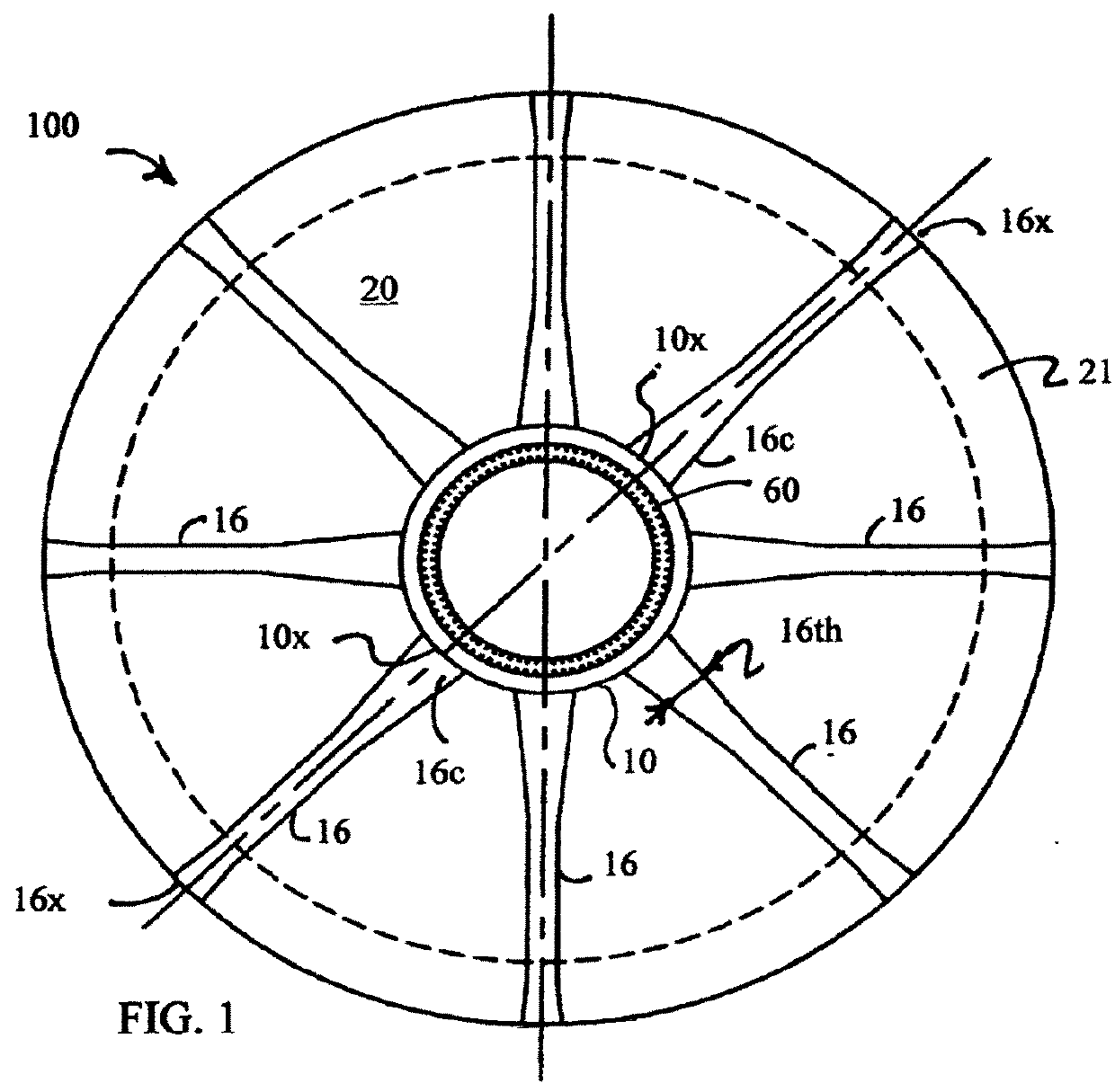
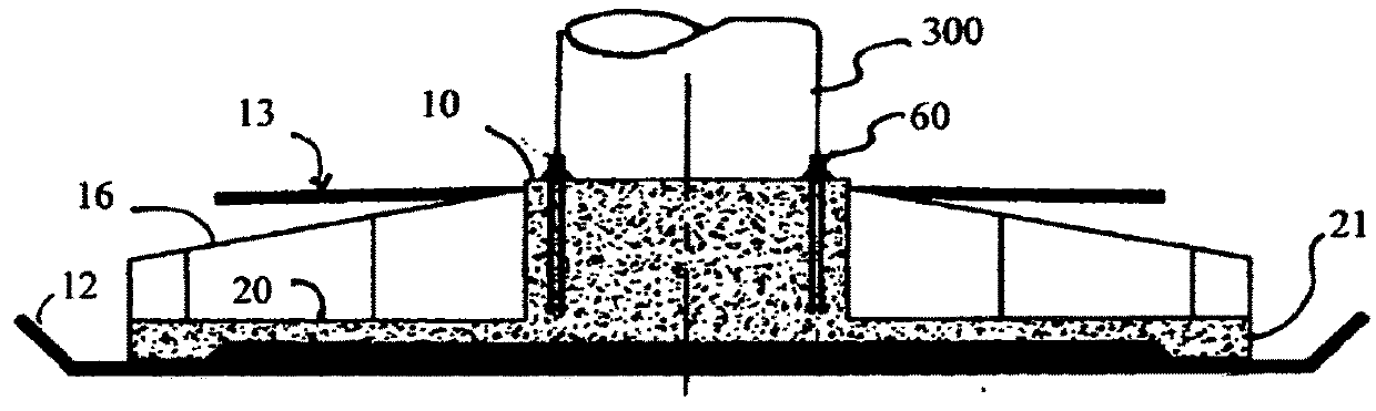
[0112]The present invention pertains to a wind turbine foundation. The foundation comprises a plurality of components, namely a central vertical pedestal, a substantially horizontal bottom support slab, and a plurality of radial reinforcing ribs extending radially outwardly from the pedestal. The ribs may be prefabricated and transported to job site, but the pedestal and support slab are poured in situ at the site out of concrete. Alternatively the ribs may be cast in situ.
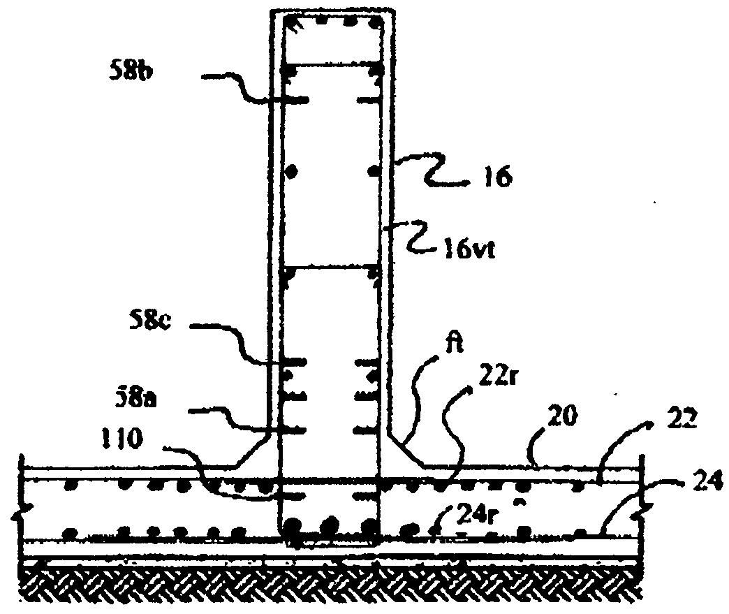
[0113]The present invention pertains to a fatigue resistant foundation 100 for wind towers which comprises a plurality of components, namely a central vertical pedestal 10, a substantially horizontal continuous bottom support slab 20 with a stiffened perimeter 21, a plurality of radial reinforcing ribs 16 extending radially outwardly from the pedestal 10 and a three-dimensional network of vertical 56, horizontal 110, 111, 112, diagonal 58b, 58c, radial 58 and circumferential 59 post-tensioning elements embedded in...
PUM
Property
Measurement
Unit
rated power
aaaaa
aaaaa
diameter
aaaaa
aaaaa
diameter
aaaaa
aaaaa
Abstract
A foundation having a central vertical pedestal, a plurality of radial reinforcing ribs extending radially outward from the pedestal. The pedestal and ribs forming a continuous monolithic structure. An anchoring system under the ribs with anchoring the foundation to the ground by anchoring elements connected to rock anchors, soil anchors, piles or the like. The foundation design reduces the weight and volume of materials used, reduces cost, and improves heat dissipation conditions during construction by having a small ratio of concrete mass to surface area thus eliminating the risk of thermal cracking due to heat of hydration.
Description
CROSS REFERENCE TO RELATED APPLICATIONS[0001]This application is a continuation of Ser. No. 15 / 530,081 filed Dec. 1, 2016, which is a continuation of application Ser. No. 15 / 137,157 filed Apr. 25, 2016 now U.S. Pat. No. 9,534,405 issued Jan. 3, 2017, which is a continuation of application Ser. No. 14 / 748,241 filed Jun. 24, 2015 now U.S. Pat. No. 9,347,197 issued May 24, 2016, which is a continuation of application Ser. No. 14 / 176,160 filed Feb. 10, 2014 now U.S. Pat. No. 9,096,985 issued Jul. 4, 2015, which is a continuation of application Ser. No. 13 / 319,083 filed Jul. 5, 2010 now U.S. Pat. No. 8,661,752 issued Mar. 4, 2014, which claims the benefit of provisional applications 61 / 215,430 filed May 5, 2009, 61 / 269,800 filed Jun. 29, 2009, 61 / 284,901 filed Dec. 28, 2009, 61 / 339,550 filed Mar. 5, 2010 and claims priority from PCT / US / 2010 / 041006 and is a continuation-in-part of patent application Ser. No. 12 / 774,727 filed May 6, 2010, which is a continuation-in-part of patent applicati...
Claims
Application Information
Patent Timeline
Application Date:The date an application was filed.
Publication Date:The date a patent or application was officially published.
First Publication Date:The earliest publication date of a patent with the same application number.
Issue Date:Publication date of the patent grant document.
PCT Entry Date:The Entry date of PCT National Phase.
Estimated Expiry Date:The statutory expiry date of a patent right according to the Patent Law, and it is the longest term of protection that the patent right can achieve without the termination of the patent right due to other reasons(Term extension factor has been taken into account ).
Invalid Date:Actual expiry date is based on effective date or publication date of legal transaction data of invalid patent.
Patent Type & Authority Applications(United States)
