Child safety seat

a child safety seat and seat technology, applied in child seats, vehicle parts, vehicle arrangements, etc., can solve problems such as the installation of child safety seats on vehicle seats that are not suitable for children, and achieve the effect of increasing the flexibility of adjustment and being safer in us

Active Publication Date: 2018-09-20
WONDERLAND SWITZERLAND AG
View PDF0 Cites 18 Cited by
  • Summary
  • Abstract
  • Description
  • Claims
  • Application Information

AI Technical Summary

Benefits of technology

[0006]The present application describes a child safety seat that can offer increased flexibility of adjustment, and is safer in use. The child safety seat includes a support base, a sliding carriage, a rotary platform, and a child seat disposed on the rotary platform. The support base is suitable for placement on a vehicle seat, and has a stop. The sliding carriage is connected with the support base, and is slidable relative to the support base between a retracted position and an extended position. The rotary platform is pivotally connected with the sliding carriage, wherein the child seat and the rotary platform are rotatable together relative to the sliding carriage and the support base between a forward facing position and a rearward facing position, and the child seat, the rotary platform and the sliding carriage are slidable together relative to the support base. Moreover, the child safety seat includes a follower part movably coupled to the rotary platform, wherein a rotational movement of the child seat and the rotary platform occurring while the sliding carriage is located in a position other than the retracted position is limited by a contact between the follower part and the stop that keeps the child seat and the rotary platform apart from the forward facing position, and the stop is located substantially outside a travel path of the follower part when the sliding carriage is in the retracted position to allow rotation of the child seat and the rotary platform to the forward facing position.

Problems solved by technology

However, the added flexibility of adjustment may induce improper installation of the child safety seat on a vehicle seat.

Method used


Image

  • Child safety seat
  • Child safety seat
  • Child safety seat

Examples


Embodiment Construction

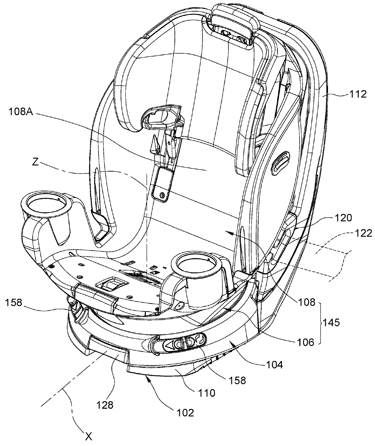
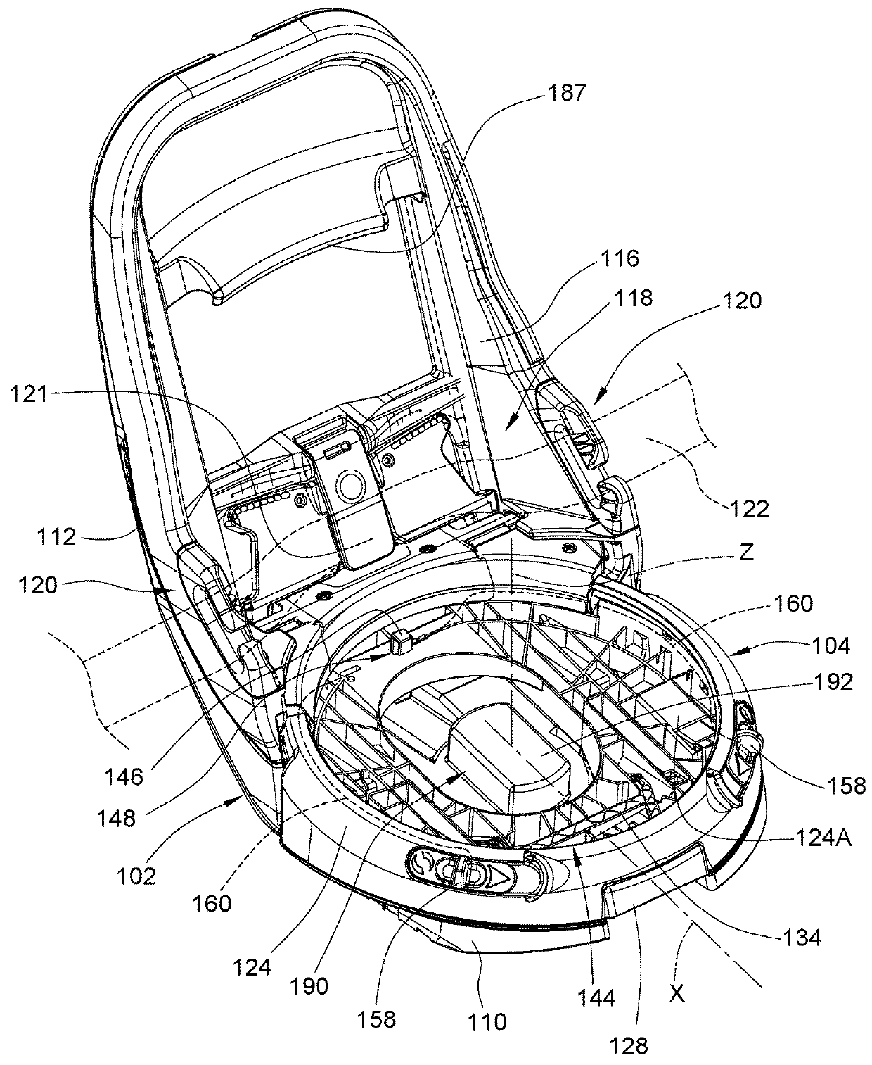
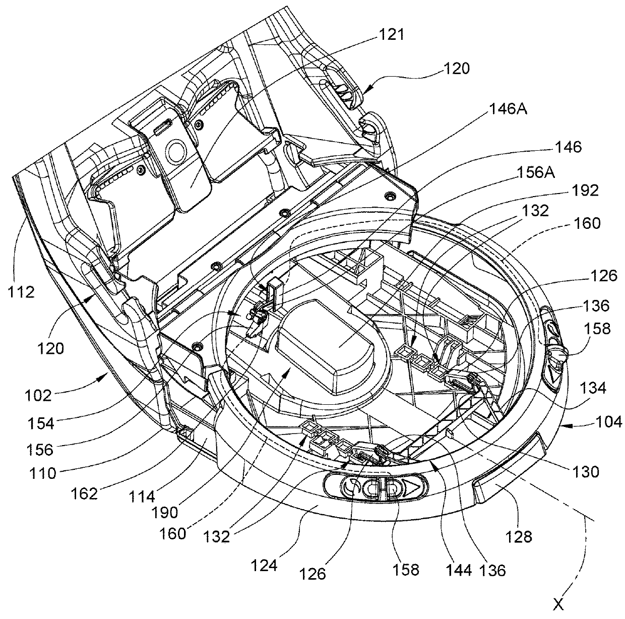
[0015]Reference is made to FIGS. 1-7 illustrating an embodiment of a child safety seat 100. Referring to FIGS. 1-7, the child safety seat 100 can include a support base 102, a sliding carriage 104, a rotary platform 106, and a child seat 108 disposed on the rotary platform 106. The support base 102 is suitable for placement on a vehicle seat to provide stable support for the child safety seat 100. According to an example of construction, the support base 102 can include a bearing portion 110 and an anchoring portion 112 connected with each other. The bearing portion 110 may include a guide track 114, and can be fixedly connected with the anchoring portion 112. The anchoring portion 112 can include a rigid shell 116, and can project above the bearing portion 110 at a rear of the bearing portion 110. The child safety seat 100 can be installed on a vehicle seat with the anchoring portion 112 abutting against a seatback of the vehicle seat and rising generally along the seatback of the ...


PUM


Abstract

A child safety seat includes a support base having a stop, a sliding carriage, a rotary platform having a follower part, and a child seat. The sliding carriage is slidable relative to the support base between a retracted and an extended position, and the child seat and the rotary platform are rotatable together relative to the sliding carriage and the support base between a forward and a rearward facing position. While the sliding carriage is in a position other than the retracted position, a rotational movement of the child seat and the rotary platform is limited by a contact between the follower part and the stop that keeps the child seat and the rotary platform apart from the forward facing position, and the stop is located outside a travel path of the follower part when the sliding carriage is in the retracted position for rotation of the rotary platform to the forward facing position.

Description

CROSS-REFERENCE TO RELATED APPLICATION(S)[0001]This patent application claims priority to U.S. Provisional Patent Application No. 62 / 473,299 filed on Mar. 17, 2017, the disclosure of which is incorporated herein by reference.BACKGROUND1. Field of the Invention[0002]The present invention relates to child safety seats.2. Description of the Related Art[0003]A child safety seat is typically used in an automobile vehicle to properly restrain a child in the event of accidental collision. It is widely known that a child safety seat that is placed in a rear facing position can provide better protection, because it can distribute crash forces over a larger portion of the body (i.e., child's head and torso). Accordingly, safety experts and car seat manufacturers usually recommend to seat children in a vehicle in a rear facing configuration until the age of 2 years old. As the child grows older, the child safety seat then may be installed in a forward facing configuration.[0004]Some child safe...

Claims


Application Information

Patent Timeline
Patent Type & Authority Applications(United States)
IPC IPC(8): B60N2/28
CPCB60N2/2869B60N2/2821B60N2/2878B60N2/26B60N2/2887B60N2/2875B60N2/2806B60N2/286B60N2/2863
Inventor ANDERSON, ROBERT SCOTTHUTCHINSON, JAMES M.F.HARMES, CLYDE V.
Owner WONDERLAND SWITZERLAND AG
Why Eureka
Try Eureka