Binocular camera and self-calibration method for binocular camera

A binocular camera, self-calibration technology, applied in the direction of image communication, stereo system, electrical components, etc., can solve the problems of dynamic calibration failure, affect the use of binocular camera, deteriorate the calibration results, etc., and achieve the effect of increasing the adjustment flexibility

Active Publication Date: 2017-05-24
UISEE SHANGHAI AUTOMOTIVE TECH LTD
View PDF6 Cites 10 Cited by
  • Summary
  • Abstract
  • Description
  • Claims
  • Application Information

AI Technical Summary

Problems solved by technology

Returning to the factory for recalibration will affect the use of binocular cameras
Dynamic calibration usually extracts the feature points in the binocular image in real time for recalibration, but in the case of inconspicuous features, it often leads to dynamic calibration failure, and even deteriorates the calibration results

Method used


Image

  • Binocular camera and self-calibration method for binocular camera
  • Binocular camera and self-calibration method for binocular camera
  • Binocular camera and self-calibration method for binocular camera

Examples


Embodiment Construction

[0026] The application will be further described in detail below in conjunction with the accompanying drawings and embodiments. It should be understood that the specific embodiments described here are only used to explain related inventions, rather than to limit the invention. For ease of description, only parts related to the invention are shown in the drawings.

[0027] It should be noted that, in the case of no conflict, the embodiments in the present application and the features in the embodiments can be combined with each other. The present application will be described in detail below with reference to the accompanying drawings and embodiments.

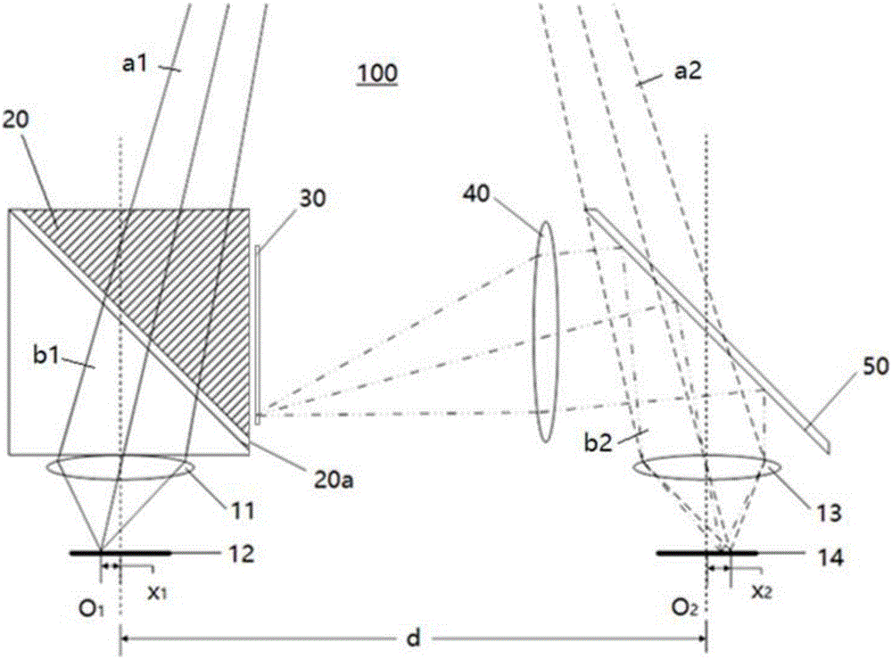
[0028] figure 1 It is a schematic diagram of a binocular camera 100 according to the first embodiment of the present invention, in which only the optical imaging part related to the invention is shown. The binocular camera 100 includes a first imaging lens 11 , a first image sensor 12 , a second imaging lens 13 and a second i...


PUM


Abstract

The invention discloses a binocular camera comprising first and second imaging lenses and first and second image sensors, wherein the binocular camera further comprises first and second optical path conversion devices arranged on object sides of the first and second imaging lenses, a calibration mark fixed relative to the first imaging lens and a calibration lens arranged between the calibration mark and the second optical path conversion device, and the calibration mark can be imaged on the second image sensor by the calibration lens and the second imaging lens. The invention further discloses a self-calibration method for the binocular camera. The self-calibration method comprises the following steps: collecting an image of the calibration mark through the second image sensor; extracting feature parameters in the image; comparing the feature parameters with a pre-stored reference benchmark; and when the difference of the feature parameters and the pre-stored reference benchmark exceeds a predetermined threshold, judging that the binocular camera needs to be marked again. According to the self-calibration method disclosed by the invention, the state in which the binocular camera needs to be marked again can be detected conveniently and effectively.

Description

technical field [0001] The present invention generally relates to a stereo camera device, in particular to a binocular camera device and a self-calibration method for the binocular camera. Background technique [0002] Binocular cameras are an increasingly attractive device capable of providing stereoscopic vision. Based on the images obtained by the binocular camera, the three-dimensional space position of the object captured by the binocular camera relative to the camera can be calculated through the principle of binocular parallax. [0003] In the three-dimensional space position calculation, the positional relationship between the two imaging lenses of the binocular camera has a great influence, so the positional relationship needs to be calibrated and calibrated. After the initial calibration and calibration, since the connection between the two imaging lenses in the binocular camera cannot be an ideal rigid body connection, the mechanical connection will slowly deform...

Claims


Application Information

Patent Timeline
Patent Type & Authority Applications(China)
IPC IPC(8): H04N13/02
CPCH04N13/246
Inventor 游宇
Owner UISEE SHANGHAI AUTOMOTIVE TECH LTD
Why Eureka
Try Eureka