Point Merge route structure-based approaching track dynamic optimization method in busy terminal area

A dynamic optimization and terminal area technology, applied in the direction of aircraft automatic landing aids, etc., can solve the problems of large workload, different aircraft intervals, and large maneuvering space, so as to achieve capacity improvement, speed up approach efficiency, and less control maneuvering adjustments Effect

Active Publication Date: 2017-03-08
CIVIL AVIATION UNIV OF CHINA
View PDF7 Cites 10 Cited by
  • Summary
  • Abstract
  • Description
  • Claims
  • Application Information

AI Technical Summary

Problems solved by technology

The disadvantages of this method are: 1) According to the control experience and the sensitivity to the heading, the controller usually adjusts the trajectory of the approaching aircraft through no less than 3 instructions, so the workload is heavy
2) The tree-like convergence structure adjusts the position of the aircraft is limited, facing the position adjustment greater than 2, it requires a large maneuvering space
3) Based on the approach track adjustment based on the tree structure, the maneuvering strategy adopted by the controller will generate a large amount of workload, so that the increase in the capacity of the terminal area is very limited
4) The applicability of the tree structure for parallel runway operation is very limited and inflexible
The advantage of the PM system is that it can make the approach trajectory in the terminal area more standardized and predictable, and the working method of the controller has been greatly improved, and it can face the large flow operating environment, but the disadvantage is the distance between aircraft Not the same, so the controller must continue to observe the dynamics of its operation, so the monitoring load is still relatively large

Method used


Image

  • Point Merge route structure-based approaching track dynamic optimization method in busy terminal area
  • Point Merge route structure-based approaching track dynamic optimization method in busy terminal area
  • Point Merge route structure-based approaching track dynamic optimization method in busy terminal area

Examples


Embodiment Construction

[0023] The method for dynamically optimizing the approach track in the busy terminal area based on the Point Merge route structure provided by the present invention will be described below in conjunction with the accompanying drawings and specific embodiments.

[0024] The approach dynamic optimization method in the busy terminal area based on the Point Merge route structure provided by the present invention comprises the following steps carried out in order:

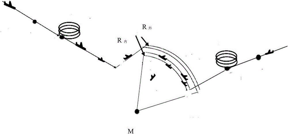
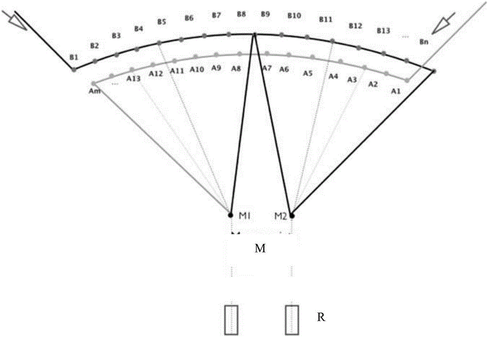
[0025] (1) if figure 1 As shown, two inner sorting arcs R are set in the terminal area 内 and two outer ordering arcs R 外 , the inner sort arc R 内 and the outer sort arc R 外 Horizontal projections separated by at least 2 nautical miles will enter the two inner sorting arcs R 内 or two outer ordering arcs R 外 All aircraft in the aircraft are classified vertically according to different wake types, and each type of aircraft occupies a separate height, that is, heavy, medium and light aircraft occupy different heights r...


PUM


Abstract

The invention provides a Point Merge route structure-based approaching track dynamic optimization method in a busy terminal area. The method comprises steps of setting two inner side sequence arcs and two outer side sequence arcs in the terminal area and vertically classifying all aircrafts entering the inner side sequence arcs or the outer side sequence arcs according to different wake flow types; landing the aircrafts in the inner side sequence arcs and the outer side sequence arcs on two adjacent and parallel runways R after the aircrafts pass a converge position point; setting a sliding window with a fixed time length and a moving interval, determining the time length and the moving interval of the sliding window according to flight time of the aircrafts in the terminal area; and then, using an intelligent algorithm to optimize time for entering the terminal area for aircrafts of which parts of or full tracks are in the sliding window, the turning moments of the aircrafts on the sequence arcs and the flight speeds of the aircrafts. The beneficial effects are that positions of the approaching aircrafts can be adjusted more flexibly and an optimal sequence strategy can be achieved.

Description

technical field [0001] The invention belongs to the technical field of approach track optimization in a busy terminal area, in particular to a dynamic optimization method for an approach track in a busy terminal area based on a PointMerge route structure. Background technique [0002] In the airport terminal area, the operation of incoming and outgoing aircraft is relatively complicated, so the research on 4D trajectory optimization of aircraft has always been the focus. The traditional terminal area track optimization method is mainly based on the traditional tree-like approach route structure. In this method, aircrafts on different routes converge multiple traffic flows into one traffic flow in twos and multiples, and finally pass the approach control Pilot radar vectoring means converges to the final approach fix (FAF). The disadvantages of this method are: 1) According to the control experience and sensitivity to the heading, the controller usually adjusts the trajector...

Claims


Application Information

Patent Timeline
Patent Type & Authority Applications(China)
IPC IPC(8): G08G5/02
CPCG08G5/02
Inventor 梁曼马兰耿增显吴维张锐
Owner CIVIL AVIATION UNIV OF CHINA
Why Eureka
Try Eureka