Ceiling Fan Motor

Active Publication Date: 2018-09-27
SUNONWEALTH ELECTRIC MACHINE IND
View PDF0 Cites 5 Cited by
  • Summary
  • Abstract
  • Description
  • Claims
  • Application Information

AI Technical Summary

Benefits of technology

[0007]To solve the above problems, the present invention provides a ceiling fan motor including a stator unit and rotor unit. The stator unit and the rotor unit do not have to rely on the axle for assembly and positionin

Problems solved by technology

Furthermore, the axle 91 suspended to the ceiling has a certain length, leading t

Method used


Image

  • Ceiling Fan Motor
  • Ceiling Fan Motor
  • Ceiling Fan Motor

Examples


Example

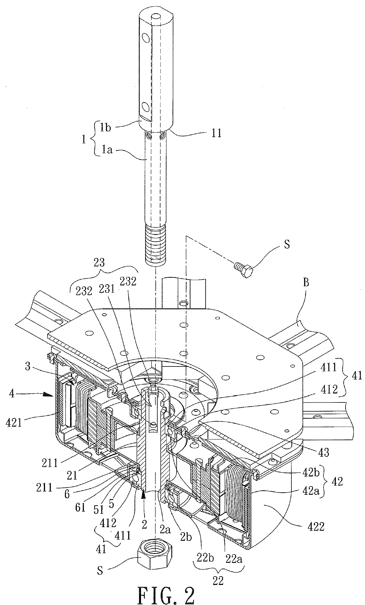
[0032]With reference to FIG. 2, a ceiling fan motor of an embodiment according to the present invention includes an axle 1, a sleeve 2, a stator unit 3, and a rotor unit 4. The stator unit 3 and the rotor unit 4 are mounted to the sleeve 2. The axle 1 is detachably mounted to the sleeve 2.

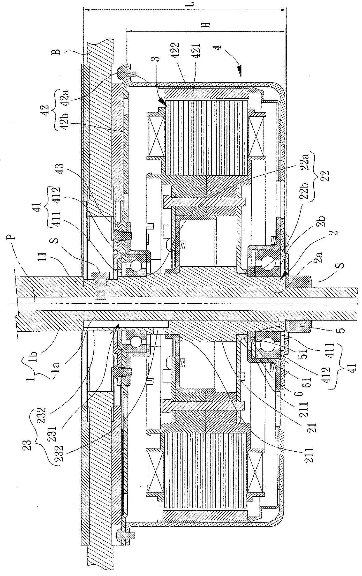
[0033]With reference to FIGS. 2 and 3, the axle 1 includes an extending section 1a and a suspension section 1b. The extending section 1a extends through and is coupled to the sleeve 2 to couple the axle 1 to the sleeve 2. The suspension section 1b is exposed outside of and located above the sleeve 2 and can be fixed to a ceiling or the like. In this embodiment, the extending section 1a is contiguous to the suspension section 1b. Furthermore, an outer diameter of the axle 1 at the extending section 1a is smaller than an outer diameter at the suspension section 1b to form a shoulder 11 by the diameter difference. The sleeve 2 has an end abutting the shoulder 11 to limit the coupling depth of the axle...


PUM


Abstract

A ceiling fan motor includes a sleeve, a stator unit fixed around the sleeve, a rotor unit rotatably mounted around the sleeve, and an axle detachably mounted to the sleeve. The axle can include an extending section and a suspension section. The extending section extends through and is coupled to the sleeve. The suspension section is exposed outside of the sleeve. The extending section can be contiguous to the suspension section. An outer diameter of the axle at the extending section can be smaller than an outer diameter at the suspension section to form a shoulder. An end of the sleeve can abut the shoulder.

Description

CROSS REFERENCE TO RELATED APPLICATIONS[0001]The application claims the benefit of Taiwan application serial No. 106109814, filed on Mar. 23, 2017, and the entire contents of which are incorporated herein by reference.BACKGROUND OF THE INVENTION1. Field of the Invention[0002]The present invention relates to a motor and, more particularly, to a motor used in a ceiling fan.2. Description of the Related Art[0003]FIG. 1 shows a conventional ceiling fan motor 9 including an axle 91, a stator unit 92, and a rotor unit 93. The ceiling fan motor 9 is fixed to a ceiling by the axle 91. The stator unit 92 is fixed around the axle 91. The axle 91 includes two shoulders 911 for abutting and positioning two bearings 931 of the rotor unit 93, permitting the rotor unit 93 to be rotatably mounted around the axle 91. An example of such a ceiling fan motor 9 is disclosed in Taiwan Utility Model M354002 entitled “CEILING FAN MOTOR.”[0004]In on-site installation, a plurality of blades (not shown) is mo...

Claims


Application Information

Patent Timeline
IPC IPC(8): F04D25/06F04D25/08H02K1/27H02K1/28H02K5/173
CPCH02K1/28H02K5/1737F04D25/062F04D25/064F04D25/0646F04D25/088H02K1/2786H02K5/00H02K1/2791F04D29/601H02K21/22H02K1/187H02K1/30H02K2213/03
Inventor HORNG, ALEXYIN, TSO-KUOYANG, KUN-TA
Owner SUNONWEALTH ELECTRIC MACHINE IND
Why Eureka
Try Eureka