Substrate container with improved substrate retainer and door latch assist mechanism

a technology of substrate retainer and substrate container, which is applied in the direction of semiconductor/solid-state device manufacturing, basic electric elements, electric devices, etc., can solve the problems of increasing the dismemberment of the actuation linkage assembly, the inability to sustain additional force loads, and the equally catastrophic effects

Active Publication Date: 2018-09-27
ENTEGRIS INC
View PDF2 Cites 0 Cited by
  • Summary
  • Abstract
  • Description
  • Claims
  • Application Information

AI Technical Summary

Benefits of technology

[0006]Various embodiments of the disclosure provide reliable, continuous biasing of the substrate retainer from a substrate retention configuration into a substrate non-retention configuration. The continuous biasing supplements, reduces, or otherwise replaces the reliance on gravity to disengage the substrate retainer from the substrates, thereby assuring safe removal of the substrates from the substrate container.
[0007]In conventional SMIF pods, the weight of the substrate retainer (i.e., gravity) provides the sole motivation for disengagement of the substrate retainer from the substrates upon removal of the door. Substrate retainers, which are typically fabricated from polymers, may produce surfaces that have an adherence quality, especially after cleaning of the substrate container within which the substrate retainer resides. The adherence quality gives the mechanism a “stickiness” that has been observed to cause the substrate retainer to hang up and to not satisfactorily disengage from the substrates. Various embodiments of the disclosure provide a biasing of the actuation linkage, continuously, so that the actuation linkage overcomes any stickiness throughout the stroke of the actuation linkage, from fully engaged to fully opened. Such continuous biasing assures that the substrate retainer will be free and clear of the wafers when the bottom door and attendant H-bar carrier is removed from the housing.
[0009]Accordingly, various embodiment of the disclosure include additional securing components that are configured to mate with existing substrate retainers and / or actuation linkages to insure the integrity of the system under increased loads due to biasing, and to increase the reliability of actuation linkages generally, whether biased or non-biased. In some embodiments, the securing components are designed to require imposition of a lateral force (such as by a prying tool) in order to become detached. Because the actuation linkage does not experience substantial lateral forces in operation, the securing components do not become dislodged by the biasing forces or the normal forces of operation, which act axially rather than laterally.
[0010]Various embodiments of the disclosure also reduce the torque requirements for installation of a door assembly into the container portion. Conventional SMIF pods can also require in excess of 7 inch-pounds (in-lbf) of torque to latch and unlatch a door from the dome. A spring-loaded arrangement is disclosed that provides a force assist to the actuation of the door latch that reduces attendant torque requirements when latching and unlatching the door assembly from the dome. For example, tests have demonstrated that, during the latching operation of the door assembly within the dome, the torque requirements for the latching operation are reduced by more than 50%.

Problems solved by technology

In some instances, a deleterious effect of applying a biasing force on the actuation linkage can be that the actuation linkage experiences forces that are greater than original design criteria, to the point that the added force loads cannot be sustained.
Such additional forces caused by the biasing may be enough for increased instances of the actuation linkage assembly to become dismembered.
Such dismemberment of the actuation linkage assembly can cause equally catastrophic effects as the aforementioned hang up of the substrate retainer.

Method used


Image

  • Substrate container with improved substrate retainer and door latch assist mechanism
  • Substrate container with improved substrate retainer and door latch assist mechanism
  • Substrate container with improved substrate retainer and door latch assist mechanism

Examples


Embodiment Construction

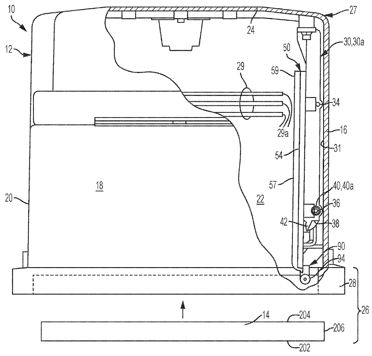
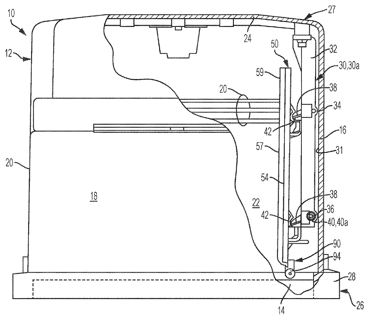
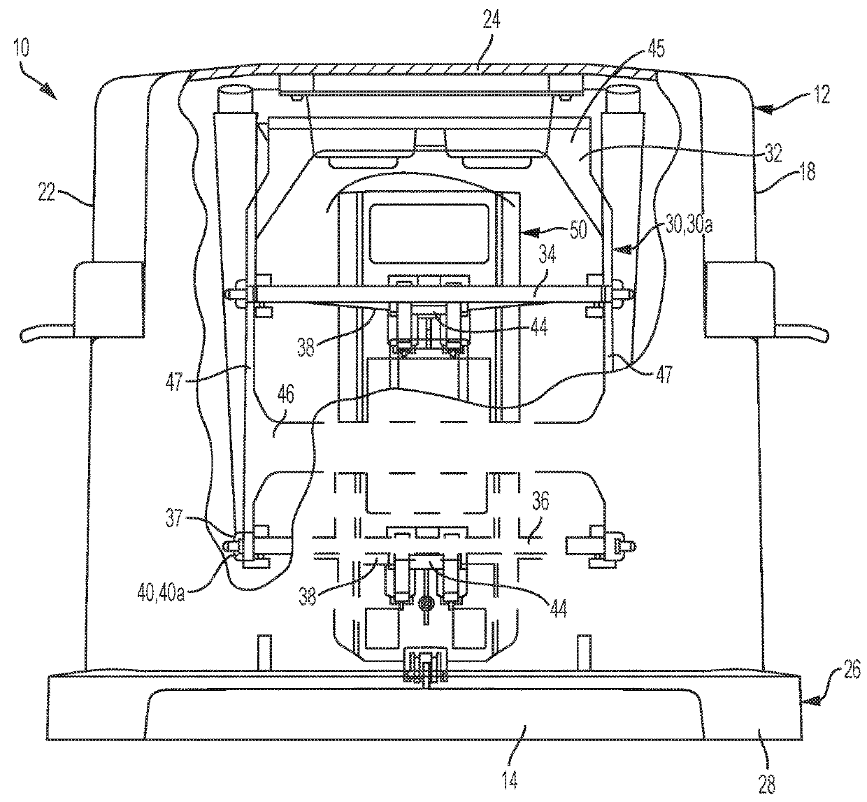
[0075]Referring to FIGS. 1 through 6, a substrate container 10 is depicted according to an embodiment of the disclosure. The substrate container 10 includes a dome or container portion 12 with an actuation linkage assembly 30, 30a mounted thereto and a door assembly 14 for selectively affecting closure of the substrate container 10. The particular embodiment depicted is a bottom opening standard mechanical interface (SMIF) pod, with the container portion 12 being generally cubical in shape and having a front wall 20, a rear wall 16, two side walls 18 and 22, a top portion 24, and a bottom assembly 26. The bottom assembly 26 includes the door assembly 14 that may be seated within a door frame 28 of the container portion 12 to form an enclosure 27. A plurality of substrates 29 having edges 29a may be housed within the enclosure 27 and may be suspended by an H-bar carrier (not depicted).

[0076]The present disclosure discloses several embodiments of actuation linkage assemblies, which ar...


PUM


Abstract

A substrate container with a substrate retainer mounted to a biased actuation linkage, and a door assembly with latch assist. Various configurations for biasing the substrate retainer in a substrate non-engagement position are disclosed. The biasing helps prevent the substrate retainer from hanging up due to friction that might otherwise counter the gravitational force that is otherwise relied upon for disengagement. The assembly may also include retention clips that positively secure the substrate retainer to the actuation linkage. The latch assist provides springs that deliver stored energy to assist in latching and unlatching the door assembly from the substrate carrier. The latch assist further provides off-center forces that bias the latching mechanism in either an unlatched or a fully latched configuration.

Description

RELATED APPLICATIONS[0001]This application claims priority to U.S. Provisional Application Ser. No. 62 / 235,682, filed Oct. 1, 2015 and titled “Substrate Container with Improved Wafer Retainer and Door Latch Assist Mechanism,” and also claims priority to U.S. Provisional Application Ser. No. 62 / 339,404, filed May 20, 2016 and titled “Substrate Container with Improved Substrate Retainer and Door Latch Assist Mechanism,” the entire contents of which are hereby incorporated by reference herein in their entireties.FIELD OF THE DISCLOSURE[0002]The disclosure relates to devices for confining substrates such as memory disks, silicon wafers, and the like for transport, storage or processing. More particularly, the disclosure relates to a substrate retention structure and door latch mechanisms.BACKGROUND[0003]Certain containers are utilized for transporting and storing batches of substrates, such as silicon wafers or magnetic disks, before, during, and after processing of the substrates. “Waf...

Claims


Application Information

Patent Timeline
Patent Type & Authority Applications(United States)
IPC IPC(8): H01L21/673
CPCH01L21/67369H01L21/67373
Inventor TIEBEN, ANTHONY MATHIUSSTRICKHOUSER, CHRISTOPHER
Owner ENTEGRIS INC
Why Eureka
Try Eureka