Vacuum transport tube vehicle, system, and method for evacuating a vacuum transport tube

a vacuum transport tube and vacuum technology, applied in transportation and packaging, locomotives, roads, etc., can solve the problems of difficulty in evacuating the tube, creating and maintaining a vacuum, or near vacuum, in the tube, and high cost of vacuum pump equipment,

Active Publication Date: 2018-10-04
THE BOEING CO
View PDF0 Cites 17 Cited by
  • Summary
  • Abstract
  • Description
  • Claims
  • Application Information

AI Technical Summary

Benefits of technology

[0007]Example implementations of this disclosure provide one or more embodiments of a vacuum transport tube vehicle, system, and method for evacuating a vacuum transport tube. As discussed in the below detailed description, embodiments of the vacuum transport tube vehicle, system, and method may provide significant advantages over existing systems and methods.

Problems solved by technology

However, evacuating the tube and creating and maintaining a vacuum, or near vacuum, in the tube may be difficult, in particular, if the tube route is several hundred miles long, or more.
Although the energy cost may be somewhat less than the vacuum pump equipment cost, as the energy may not vary with the evacuation time because the total amount of energy required to evacuate the tube may remain the same, the energy cost to achieve and maintain the vacuum may still be high.
Although the cost of the vacuum pump equipment may be spread over multiple routes, the cost of the vacuum pump equipment is still high.
In addition, the vacuum pump equipment may wear out over time and may need to be maintained, repaired, and / or eventually replaced.
This may increase the costs of maintenance, repair, and replacement for such known system.
Further, the vacuum pump equipment may be heavy and may increase the overall weight of the vacuum tube vehicle, which may, in turn, affect the speed at which the vacuum tube vehicle moves or travels through the tube.
Such pressure seals may be costly to use and install, and may, in turn, increase the overall cost of manufacturing.
Such close tolerance requirements may increase the cost and complexity of manufacturing the vacuum tube vehicle used to evacuate the tube.

Method used


Image

  • Vacuum transport tube vehicle, system, and method for evacuating a vacuum transport tube
  • Vacuum transport tube vehicle, system, and method for evacuating a vacuum transport tube
  • Vacuum transport tube vehicle, system, and method for evacuating a vacuum transport tube

Examples


example 1

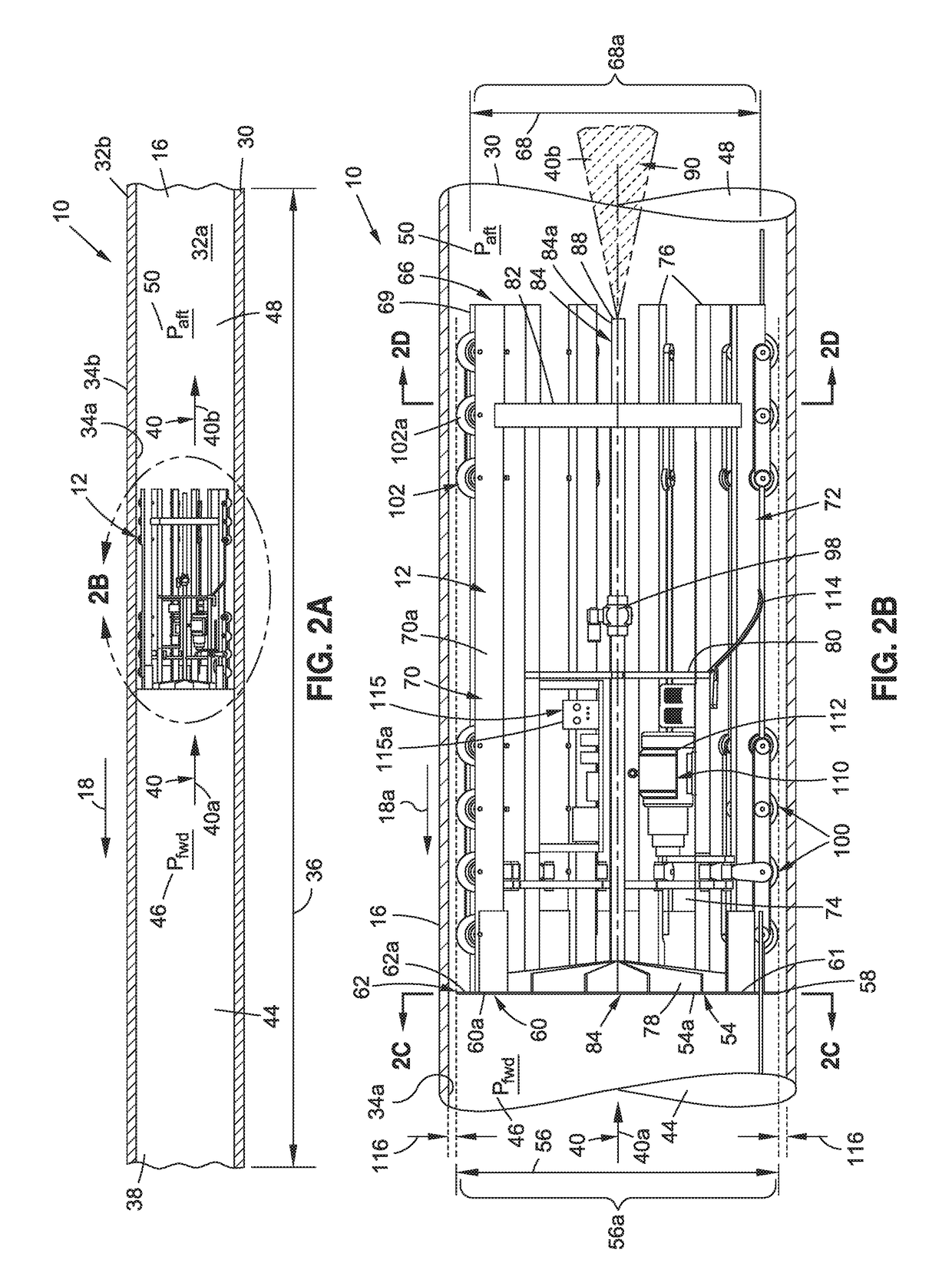
[0103]FIG. 6 is a schematic illustration of a velocity 142, such as a forward velocity 142a, from 0 (zero) second to 1 (one) second, through the vacuum transport tube 16, for an embodiment of a vacuum transport tube vehicle 12, such as a car 13, of an embodiment of the vacuum tube vehicle system 10 of the disclosure. FIG. 6, as well as FIG. 2C, shows the quantities that may be used to calculate the pressures 43 (see FIGS. 7A-7B), such as the forward pressure (Pfwd) 46 and the aft pressure (Paft) 50.

[0104]The following example was prepared to illustrate the concept.

[0105]The gap area (Agap) 120 (see FIGS. 2C, 6) was the gap distance (d) 118 (see FIG. 2C) multiplied by a perimeter 35 (see FIG. 16) of the vacuum transport tube vehicle 12. For a vacuum transport tube outer diameter 31 (see FIGS. 2C, 16) equal to 14.0 feet and a gap distance 118 (see FIG. 2C) of 0.25 inches (0.020833 ft), the gap area 120 (see FIG. 2C) was 0.916 square feet.

Agap=(π)(D)(d)=(3.14159)(14.0)(0.020833)=0.916 ...

example 2

[0117]The operation of the vacuum transport tube vehicle 12 falls into three regimes, including orifice control 144 (see FIGS. 7A-13), speed control 146 (see FIGS. 7A-13), and constant pressure ratio 148 (see FIGS. 7A-13).

[0118]With respect to orifice control 144 (see FIGS. 7A-13), when starting out at ambient pressure 46a (see FIG. 3A), it is the case that using an annular gap 116 (see FIG. 2C) of only 0.25 inches results in a large delta pressure 52 (see FIGS. 11A-11B), or pressure differential, between the forward space 44, i.e., forward volume, and the aft space 48, i.e., aft volume. A large delta pressure 52, or pressure differential, may result in a large force being applied to the forward surface 60 (see FIG. 2B) of the vacuum transport tube vehicle 12 (see FIG. 2B). If a horsepower is limited to a certain value, this forces the speed of the vacuum transport tube vehicle 12, such as the first car 13a (see FIG. 4A) to be quite slow, perhaps 2 ft / sec (two feet per second) or 3 ...

example 3

[0130]With regard to speed control 146 (see FIGS. 7A-13), at some point, the orifice diameter 92 (see FIG. 2C) becomes zero, or less than zero, and the orifice 84 (see FIG. 2C) may be closed. If the annular gap 116 (see FIG. 2C) was maintained at the same value, the power required 96c (see FIG. 12A) will decrease if the speed 94 (see FIG. 16) is held constant. If one desires to maintain the same horsepower required, the speed may be increased. The speed at which this occurs was given by the following equation:

vpiston=P+(Vgap)(Pfwd) / (Pfwd)(Apiston head)=330,000+(1007.6)(2116.7) / (2116.7)(153.94)=8.932 ft / sec (feet per second)

[0131]The rest of the quantities could be calculated using the equations from Example 1.

[0132]With regard to the constant pressure ratio 148 (see FIGS. 7A-13), it may be desirable to limit the top speed of the vacuum transport tube vehicle 12. In this case, the equations from Example 1 could be used.

[0133]Now referring to FIGS. 7A-12B, FIGS. 7A-12B show the values...


PUM


Abstract

A vacuum transport tube vehicle, system, and method for evacuating a vacuum transport tube are provided. The vehicle has a first end having a first end outer surface. An annular gap is formed between the first end outer surface and an inner surface of the vacuum transport tube. The vehicle has a second end having a second end outer diameter, and a body in the form of a piston with a structural framework. The vehicle has an orifice extending from a first inlet portion in the first end to a second outlet portion of the vehicle. The vehicle has a drive assembly coupled to the body, and a power system. The vehicle evacuates the vacuum transport tube by reducing pressure within the tube with each successive vehicle pass through the tube, until a desired pressure is obtained and a vacuum is created in the interior of the tube.

Description

BACKGROUND1) Field of the Disclosure[0001]The disclosure relates generally to systems and methods for evacuating tubes to create a vacuum, and more particularly, to systems and methods for evacuating air from tubes used for high-speed vacuum tube transportation systems.2) Description of Related Art[0002]The concept of high-speed travel through tubes has been known for years. Recently, there has been a renewed and increased interest in and investigation of high-speed vacuum or pneumatic tube transportation systems, in which a vehicle travels through an evacuated tube or near evacuated tube near the surface of the earth at high speeds, e.g., 200-2000 miles per hour (mph) average speed. The high speeds may be enabled by a magnetic levitation (“mag-lev”) propulsion system that eliminates or greatly reduces rolling friction, and by evacuating the tube of air so that aerodynamic drag is eliminated or greatly reduced.[0003]However, evacuating the tube and creating and maintaining a vacuum,...

Claims


Application Information

Patent Timeline
Patent Type & Authority Applications(United States)
IPC IPC(8): B61B13/12B61B13/10B61C3/00B61B13/08
CPCB61B13/122B61B13/08B61C3/00B61B13/10
Inventor GRIP, ROBERT ERIKDEHAAN, MARK A.VASSBERG, JOHN C.ROTHAUPT, TED K.
Owner THE BOEING CO
Why Eureka
Try Eureka