
Systems and methods for stabilisation of aerial vehicles

a technology for stabilising systems and aerial vehicles, applied in the field of aerial vehicles, can solve the problems of unstable aircraft, difficult speed up and slow down, etc., and achieve the effects of reducing the rotational mass, and reducing the number of aircraft to be lifted

Inactive Publication Date: 2018-10-04
ALTUS IP LTD
View PDF28 Cites 20 Cited by
  • Summary
  • Abstract
  • Description
  • Claims
  • Application Information

AI Technical Summary

Benefits of technology

The patent is about improvements to multirotor aircraft, specifically UAVs with fixed-pitch rotors. The use of a first propeller with more blades can cause a wave frequency offset that improves the effectiveness of a second propeller. This allows for the use of a smaller diameter propeller, which can be more responsive but may have lower power efficiency. Overall, the patent aims to improve the performance and responsiveness of multirotor aircraft.

Problems solved by technology

Larger propellers are harder to speed up and slow down quickly in comparison with smaller propellers, due to their rotational mass and are therefore often too slow to react to inputs from the autopilot resulting in an unstable aircraft particularly in windy conditions.

Method used


Image

  • Systems and methods for stabilisation of aerial vehicles
  • Systems and methods for stabilisation of aerial vehicles
  • Systems and methods for stabilisation of aerial vehicles

Examples


Embodiment Construction

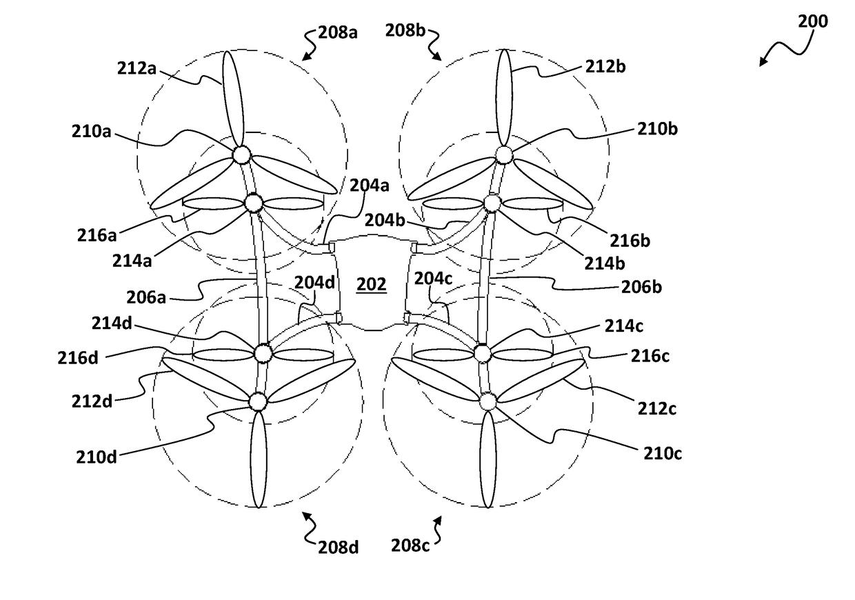
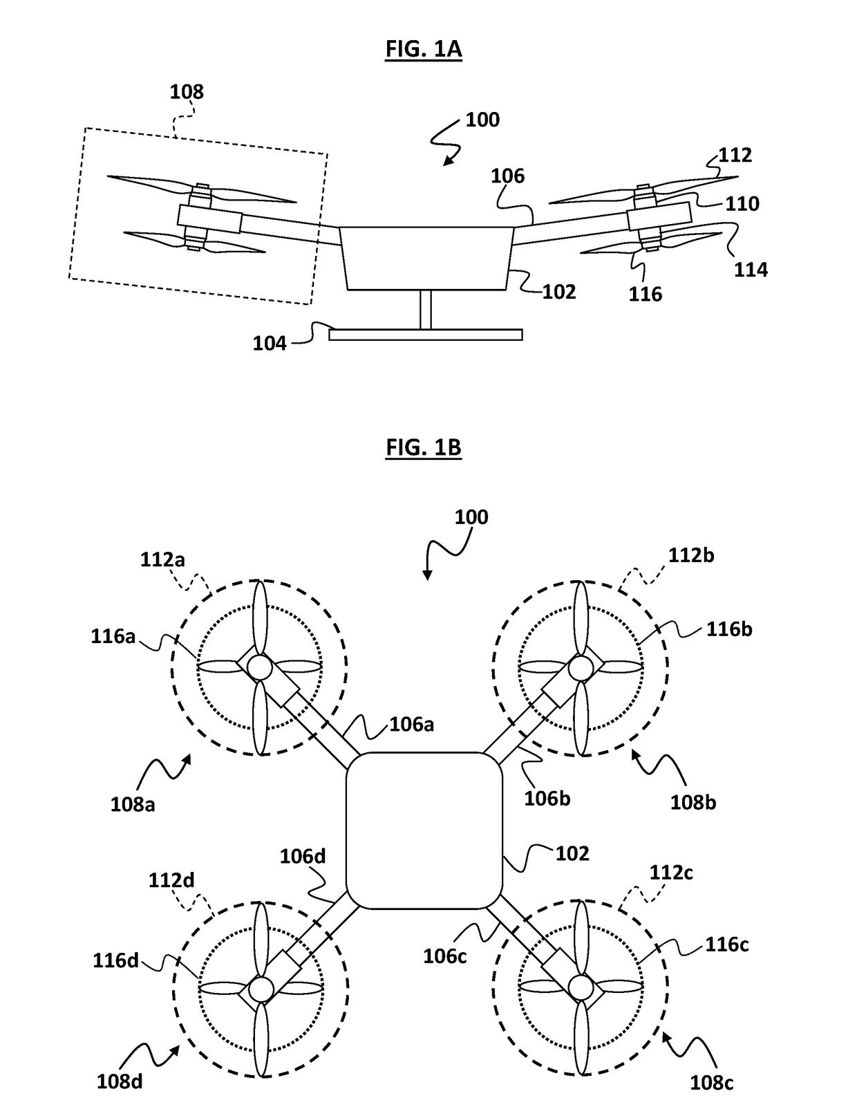
[0056]FIG. 1A and FIG. 1B illustrate an unmanned multirotor aircraft 100 in an “X8” configuration, herein referred to as “UAV 100”. As seen in FIG. 1A, the airframe of the UAV 100 includes a hull 102 supported by a landing base 104. Arms 106 (labelled arms 106a-d in FIG. 1B) extend from the hull 102, with rotor assemblies 108 (labelled rotor assemblies 108a-d in FIG. 1B) secured to the distal ends of the arms 106. It should be appreciated that while the arms 106 are illustrated as being pitched up from the hull 102, this is not intended to be limiting to all embodiments.

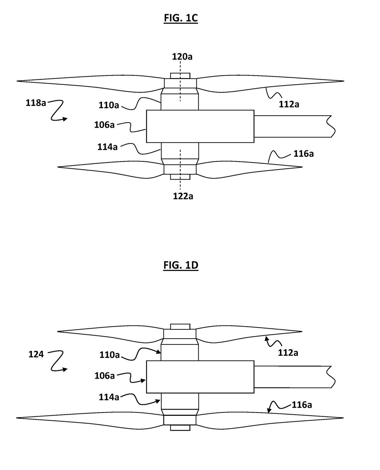
[0057]Each rotor assembly 108 includes a top motor 110 (labelled top motors 110a-d in FIG. 1B), to which a top propeller 112 (labelled top propellers 112a-d in FIG. 1B) is secured. Each rotor assembly 108 includes a bottom motor 114 (labelled bottom motors 114a-d in FIG. 1B), to which a bottom propeller 116 (labelled bottom propellers 116a-d in FIG. 1B) is secured. Referring to FIG. 1B, it may be seen that in this ex...


PUM


Abstract

A rotor assembly for a multirotor aircraft, and a multirotor aircraft, are disclosed herein. The rotor assembly has a first motor having a first axis of rotation and a first propeller connected to the first motor. The rotor assembly has a second motor having a second axis of rotation, and a second propeller connected to the second motor. The second propeller is smaller in length than the first propeller. The first motor and the first propeller produce a greater proportion of a total lift thrust of the rotor assembly than the second motor and the second propeller. The multirotor aircraft includes an airframe and a plurality of the rotor assemblies mounted to the airframe.

Description

TECHNICAL FIELD[0001]The present disclosure relates to aerial vehicles, more particularly unmanned multirotor rotorcraft, and rotor assemblies, systems, and methods for their stabilisation in flight.STATEMENT OF CORRESPONDING APPLICATIONS[0002]This application is based on the provisional specification filed in relation to New Zealand Patent Application Number 712108, the entire contents of which are incorporated herein by reference.BACKGROUND[0003]Unmanned aerial vehicles (UAVs), particularly rotorcraft, are increasingly being deployed in a wide range of applications, including: industrial surveying, construction, mining, stockpiling, photogrammetry, aerial photography, cinematography and video, live streaming, newsgathering, multispectral analysis for vegetation, security and surveillance, asset inspection, transmission and pipeline inspection.[0004]It is generally desirable to increase the flight time of a UAV while carrying a payload (such as an imaging device), and thereby impro...

Claims


Application Information

Patent Timeline
Patent Type & Authority Applications(United States)
IPC IPC(8): B64C39/02B64C11/48B64C17/00B64C27/10B64C27/32
CPCB64C39/024B64C11/48B64C17/00B64C27/10B64C27/32B64C2201/027B64C2201/108B64C2201/14B64U2201/00B64U10/14B64U50/30B64U30/24
Inventor MITCHELL, SHAUN GORDON
Owner ALTUS IP LTD
Learn More