Downhole tools having controlled degradation and method

a technology of downhole tools and degradation, applied in earth drilling and mining, sealing/packing, wellbore/well accessories, etc., can solve the problems of general time-consuming and expensive operations, uncontrollable disintegration period, and inability to control the disintegration process, so as to facilitate the degradation of downhole tools

Active Publication Date: 2018-10-04
BAKER HUGHES INC
View PDF0 Cites 16 Cited by
  • Summary
  • Abstract
  • Description
  • Claims
  • Application Information

AI Technical Summary

Benefits of technology

[0004]A downhole assembly includes a downhole tool including a degradable-on-demand material including: a matrix material; and, a unit in contact with the matrix material. The unit includes a core including an energetic material configured to generate energy upon activation to facilitate degradation of the downhole tool; and, an activator disposed in contact with the core, the activator including a triggering system having an electrical circuit and an igniter within the electrical circuit, the electrical circuit having an open condition and a closed condition, the electrical circuit configured to be in the closed condition after movement of an object downhole that engages directly or indirectly with the triggering system, and the igniter arranged to ignite the energetic material in the closed condition of the electrical circuit. In the open condition of the electrical circuit the igniter is inactive, and in the closed condition of the electrical circ

Problems solved by technology

Oil and natural gas wells often utilize wellbore components or tools that, due to their function, are only required to have limited service lives that are considerably less than the service life of the well.
Disposal of components or tools has conventionally been done by milling or drilling the component or tool out of the wellbore, which are generally time consuming and expensive operations.
One challenge for the self-disintegrating downhole tools is that the disintegra

Method used


Image

  • Downhole tools having controlled degradation and method
  • Downhole tools having controlled degradation and method
  • Downhole tools having controlled degradation and method

Examples


embodiment 1

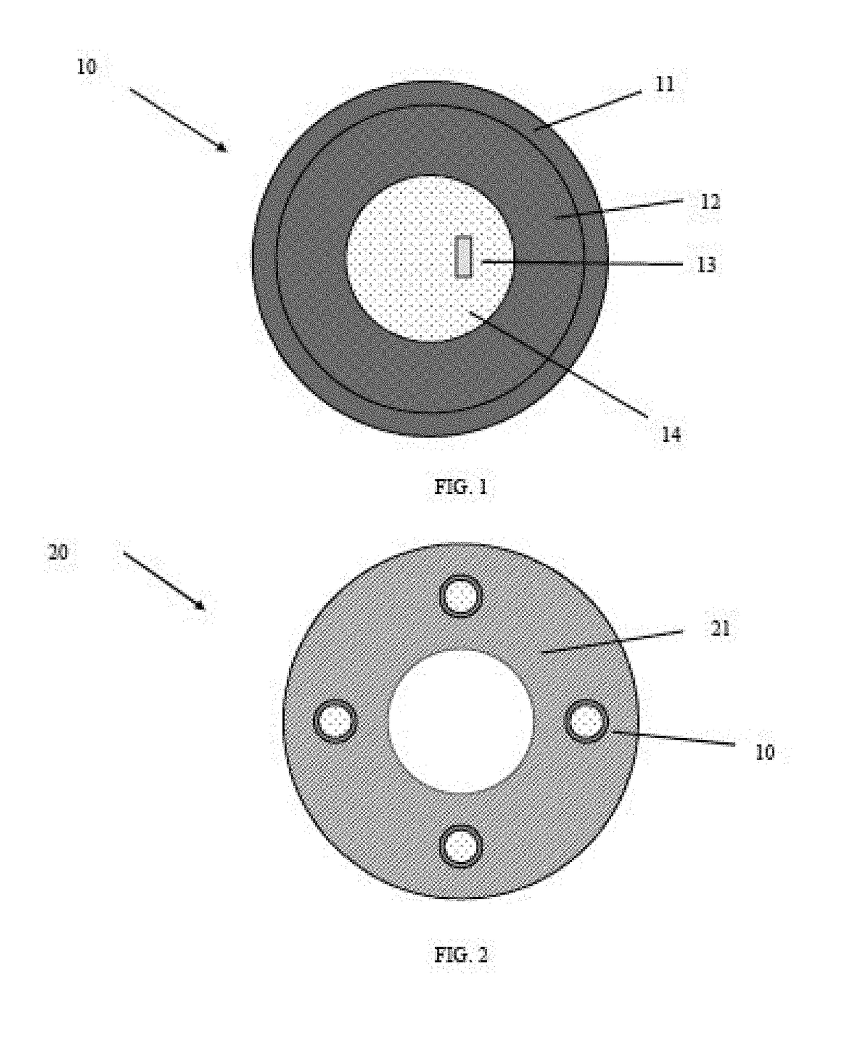
[0066]A downhole assembly includes a downhole tool including a degradable-on-demand material including: a matrix material; and, a unit in contact with the matrix material. The unit includes a core including an energetic material configured to generate energy upon activation to facilitate degradation of the downhole tool; and, an activator disposed in contact with the core, the activator including a triggering system having an electrical circuit and an igniter within the electrical circuit, the electrical circuit having an open condition and a closed condition, the electrical circuit configured to be in the closed condition after movement of an object downhole that engages directly or indirectly with the triggering system, and the igniter arranged to ignite the energetic material in the closed condition of the electrical circuit. In the open condition of the electrical circuit the igniter is inactive, and in the closed condition of the electrical circuit the igniter is activated.

embodiment 2

[0067]The downhole assembly as in any prior embodiment or combination of embodiments, further including a switch in the triggering system, the switch arranged to close in response to movement of the object downhole.

embodiment 3

[0068]The downhole assembly as in any prior embodiment or combination of embodiments, wherein closure of the switch closes the electrical circuit.


PUM


Abstract

A downhole assembly includes a downhole tool including a degradable-on-demand material including: a matrix material; and, a unit in contact with the matrix material. The unit includes a core including an energetic material configured to generate energy upon activation to facilitate degradation of the downhole tool; and, an activator disposed in contact with the core, the activator including a triggering system having an electrical circuit and an igniter within the electrical circuit, the electrical circuit having an open condition and a closed condition, the electrical circuit configured to be in the closed condition after movement of an object downhole that engages directly or indirectly with the triggering system, and the igniter arranged to ignite the energetic material in the closed condition of the electrical circuit. In the open condition of the electrical circuit the igniter is inactive, and in the closed condition of the electrical circuit the igniter is activated.

Description

CROSS REFERENCE TO RELATED APPLICATIONS[0001]The present application is a continuation-in-part of U.S. patent application Ser. No. 15 / 472,382, filed Mar. 29, 2017, which is hereby incorporated by reference in its entirety.BACKGROUND[0002]Oil and natural gas wells often utilize wellbore components or tools that, due to their function, are only required to have limited service lives that are considerably less than the service life of the well. After a component or tool service function is complete, it must be removed or disposed of in order to recover the original size of the fluid pathway for use, including hydrocarbon production, CO2 sequestration, etc. Disposal of components or tools has conventionally been done by milling or drilling the component or tool out of the wellbore, which are generally time consuming and expensive operations.[0003]Recently, self-disintegrating downhole tools have been developed. Instead of milling or drilling operations, these tools can be removed by dis...

Claims


Application Information

Patent Timeline
IPC IPC(8): E21B41/00E21B23/04E21B31/00E21B31/107E21B41/02
CPCE21B41/0085E21B23/04E21B31/002E21B31/1075E21B41/02E21B23/03E21B29/00E21B33/0375C22C18/00C22C19/00E21B34/066E21B29/02E21B31/107E21B33/134E21B33/12
Inventor ZHANG, ZHIHUIXU, ZHIYUESHYU, GOANG-DINGFLORES PEREZ, JUAN CARLOSDOANE, JAMESXU, YINGQING
Owner BAKER HUGHES INC
Why Eureka
Try Eureka