Mechanical flywheel for bowed rotor mitigation

Active Publication Date: 2018-10-04
THE BOEING CO
View PDF6 Cites 15 Cited by
  • Summary
  • Abstract
  • Description
  • Claims
  • Application Information

AI Technical Summary

Benefits of technology

[0015]In yet a further embodiment, the second generator converts rotational energy of the flywheel into the second electrical energy used to power to an aircraft electrical system during times of peak electrical loading of the electrical system. A computer connect

Problems solved by technology

The rub causes vibrations (manifested as disconcerting noise in the aircraft cabin) or even damage to the aircraft (e.g., engine damage, damage to the engine case lining, or damage to other accessories).
Thus, the overriding need to reduce fuel consumption renders wider cold build clearances less desirable.
Indeed, as ever tighter cold build clearances are implemented, the problems caused by engine rub will become more severe.
However, these architecture changes would add weight and manufacturing cost to the engine.
However, conventional methods for providing power to the ETM or the engine so as to straighten the bow can be problematic.
Furthermore, auxiliary power unit (APU) power on the aircraft is not always available to power the engine or ETM because some airports limit APU use at gates due to emissions and noise c

Method used


Image

  • Mechanical flywheel for bowed rotor mitigation
  • Mechanical flywheel for bowed rotor mitigation
  • Mechanical flywheel for bowed rotor mitigation

Examples


Example

FIRST EXAMPLE

Gearbox Installation

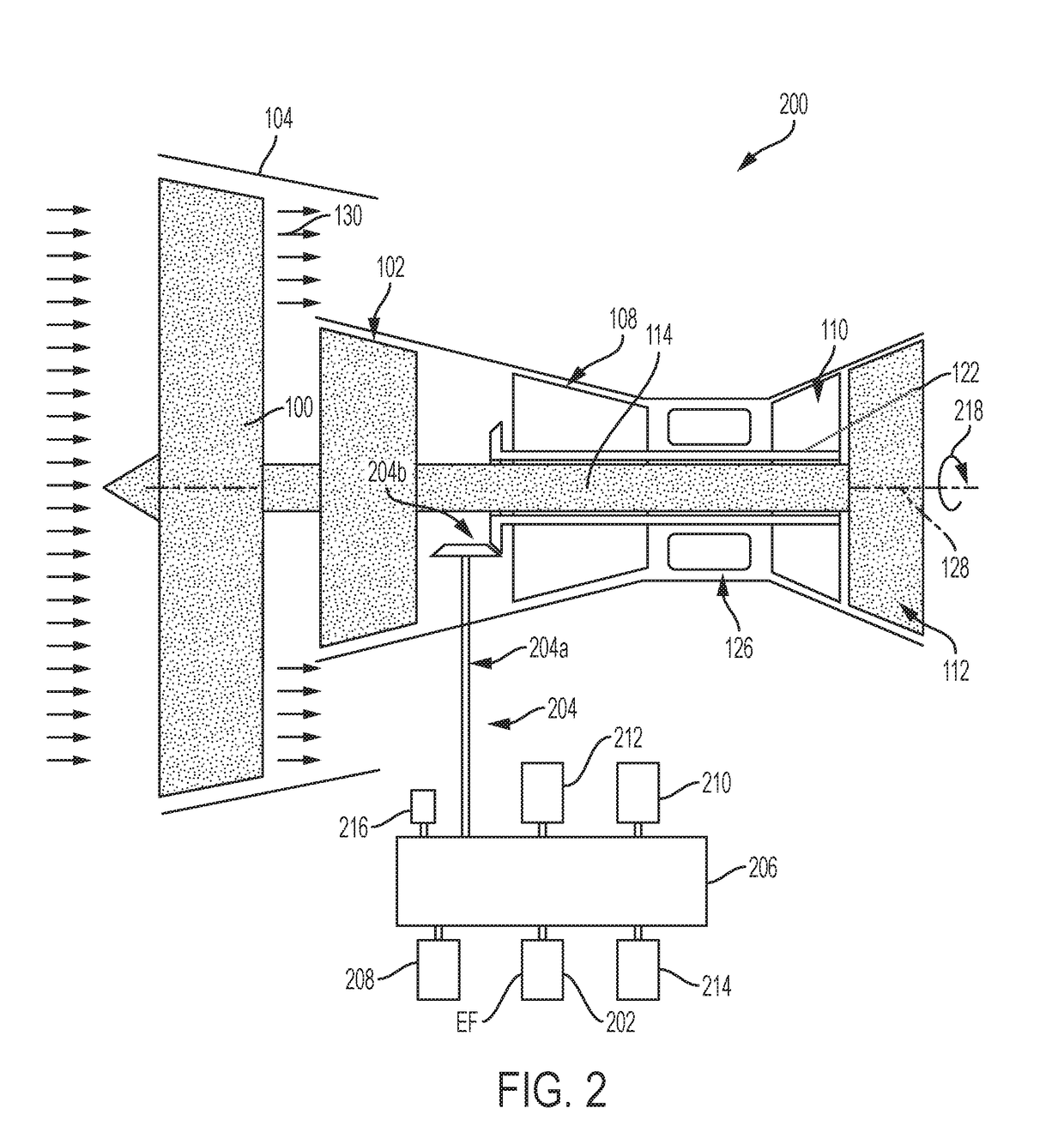
[0031]FIG. 2 illustrates an apparatus or system, comprising a gas turbine engine 200 having a rotor (HP compressor 108) including a rotor shaft 122; a flywheel 202; and a first transmission 204 (comprising tower or drive shaft 204a and bevel gears 204b) connecting the rotor's shaft 122 to an accessory gearbox 206. The flywheel 202 is connected to and installed on the gearbox 206. Also shown are a generator 208, fuel pump 210, lube module 212, hydraulic pump 214, and a permanent magnet generator (PMG) 216 connected to the gearbox 206. In one embodiment, the gearbox is attached to the casing 106.

Example

SECOND EXAMPLE

Mechanical-Electrical Energy Conversion

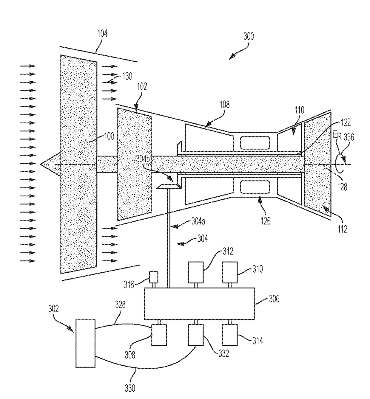
[0032]FIG. 3A illustrates an apparatus or system, comprising a gas turbine engine 300 having a rotor (HP compressor 108) including a rotor shaft 122); a housing 302 comprising a flywheel and motor generator; a first transmission 304 (comprising tower shaft 304a and bevel gears 304b) connecting the rotor shaft 122 to the gearbox 306, and a first generator 308 connected to the gearbox 306. Also shown are fuel pump 310, lube module 312, hydraulic pump 314, and PMG 316 connected to the gearbox 306.

[0033]FIG. 3B illustrates the motor-generator in housing 302 typically comprises a second generator 318 and a first motor 320, a second transmission 322 connecting the flywheel 324 to the flywheel motor 320, and a third transmission 326 connecting the flywheel 324 to the second generator 318. An electrical connection 328 connects the flywheel motor 320 to the first generator 308 so that energy can be transferred to charge the flywheel 324. T...

Example

THIRD EXAMPLE

Load Leveling

[0043]The aircraft's electrical system 334 (e.g., powering air conditioning, cabin pressurization, and plumbing) adds various electrical loads during operation of the aircraft. Typically, some of the engine's rotational energy is converted into electrical energy in order to handle these additional loads. In this case, the engine then has to burn more fuel to maintain its original rotation speed. Consequently, the engine must be operated in such a way (i.e., with high enough speed) that it can withstand a sudden electrical load and maintain stability.

[0044]In one embodiment, the airplane extracts electrical power form the flywheel to help power the electrical systems on the aircraft at various times, e.g., during peak electrical demands. This alleviates the burden on the engine, enabling less fuel burn and lower engine speeds for most of the flight while still accommodating sudden electrical loads applied to the electrical system.

[0045]Peak electrical demand...


PUM


Abstract

A mechanical flywheel used to power an aircraft system. In one example, the flywheel is used to rotate a rotor shaft in the aircraft's engine and prevent bowing of the rotor shaft caused by a thermal gradient. In another example, the mechanical flywheel provides electrical power at peak demand times. In yet another example, the flywheel is used as a load source or sink by the engine's control system so as to aid engine operability and engine acceleration rates during abnormal flight conditions.

Description

BACKGROUND1. Field[0001]The present disclosure relates to a system for storing and using rotational energy generated in an aircraft gas turbine engine.2. Description of the Related Art[0002]FIG. 1 illustrates an aircraft engine comprising a fan 100, a low pressure (LP) compressor 102, a fan case 104, an engine casing 106, a High Pressure (HP) compressor 108, a HP turbine 110, a LP turbine 112, and a LP shaft 114 connecting the LP compressor 102 and the LP turbine 112. After engine shutdown on the ground, residual hot air 116 in the engine core rises 118 and is trapped by the engine casing 106. As the hot air rises 118, the upper portion 120 of the HP compressor's (engine's rotor) 108 rotor shaft 122 becomes hotter than the lower portion 124 of the rotor shaft 122 and causes uneven cooling and thermal deformation of the engine rotor shaft 122 (i.e., rotor bowing, where the upper portion 120 of the rotor shaft 122 becomes longer than the lower portion 124). Upon engine restart (e.g., ...

Claims


Application Information

Patent Timeline
IPC IPC(8): F02C6/14F01D15/10F02C7/20F02C9/26F01D15/12B64D27/18F01D25/34
CPCF02C6/14F01D15/10F02C7/20F02C9/26B64D2221/00B64D27/18F01D25/34F05D2220/323F01D15/12B64D27/16B64D41/00F02C3/107F02C7/32F02C7/36F02K3/06F05D2260/43F05D2260/941Y02T50/50Y02T50/60B64D27/10
Inventor JACKOWSKI, JASON J.KARNOFSKI, KENT E.
Owner THE BOEING CO
Why Eureka
Try Eureka