Heat sink

a heat sink and heat sink technology, applied in the field of heat sinks, can solve the problems of insufficient thermal diffusion on inability to and insufficient thermal diffusion in the surface of the heat receiving plate, so as to improve the cooling performance of the heat sink with the heat pipes formed from the tube body, improve the heat dissipation efficiency of the heat dissipation fins

Active Publication Date: 2018-10-04
FURUKAWA ELECTRIC CO LTD
View PDF8 Cites 7 Cited by
  • Summary
  • Abstract
  • Description
  • Claims
  • Application Information

AI Technical Summary

Benefits of technology

[0013]According to an aspect of the present disclosure, tubular-heat pipes are provided in a plurality of layers in the vertical direction to the surface of the heat receiving plate. Since with respect to at least two of these layers, the positions of the heat pipes on the surface of the heat receiving plate are not identical to each other, the heat sink has excellent thermal diffusion characteristics in the planar direction of the heat receiving plate of the heat sink, that is, in a parallel direction to the surface of the heat receiving plate of the heat sink, so that the whole in the planar direction of the heat receiving plate is heat equalized. Since the heat sink as the whole in the planar direction of the heat receiving plate is heat equalized, heat dissipation efficiency of the heat dissipation fins thermally connected to the heat receiving plate is improved and consequently cooling performance of the heat sink with the heat pipes formed from the tube body is improved.
[0014]According to an aspect of the present disclosure, since the heat conductor is provided around the heat pipes, thermal diffusion characteristics of the heat sink in the parallel direction to the surface of the heat receiving plate is further increased, as a result, heat dissipation efficiency of the heat dissipation fins is further improved.
[0015]According to an aspect of the present disclosure, since the shape of the heat pipe is flat, in an aspect in which a contact area between the heat pipe and another member is large, it possible to thermally connect the heat pipe and other member. Therefore, since heat transfer from the heat receiving plate to the heat dissipation fins can be smoothened and thermal resistance can also be reduced, heat dissipation efficiency of the heat dissipation fins is further improved. In addition, since the shape of the heat pipe is flat, even when the heat pipes are provided in a plurality of layers, an increase in dimension in the vertical direction to the surface of the heat receiving plate can be prevented.

Problems solved by technology

In an aspect in which heat pipes are provided in a single layer, due to constraints on the bending of the heat pipes, constraints on the number of the heat pipes that can be arranged on a heat source and the like, thermal diffusion on the surface of the heat receiving plate may be insufficient.
Therefore, in the above-mentioned heat sink, the heat dissipation fins erected on the surface of the heat receiving plate may not sufficiently contribute to heat dissipation in its entirety, as a result, there is a problem such that it is impossible to improve heat dissipation efficiency of the heat dissipation fins.
However, in Japanese Laid-Open Patent Publication No. 10-38483 using the meandering thin tunnel heat pipes, since the heat pipes are provided by forming continuous flow paths rather than tube bodies and the heat pipes operate only in the vicinity just above a heating element, not all of the heat pipes stretched over a plate function.
Therefore, also in Japanese Laid-Open Patent Publication No. 10-38483, thermal diffusion in a surface of the composite plate heat pipe may be still insufficient.
In addition, since the composite plate heat pipe of Japanese Laid-Open Patent Publication No. 10-38483 is not an aspect in which heat dissipation fins are provided, sufficient cooling capability cannot be obtained.
From the above, the composite plate heat pipe of Japanese Laid Open Patent Publication No. 10-38483 still has a problem that heat dissipation efficiency cannot be sufficiently improved.

Method used


Image

  • Heat sink
  • Heat sink
  • Heat sink

Examples


example

[0066]Next, examples of the present disclosure will be described. However, the present disclosure is not limited to these examples unless the invention departs from the spirit thereof.

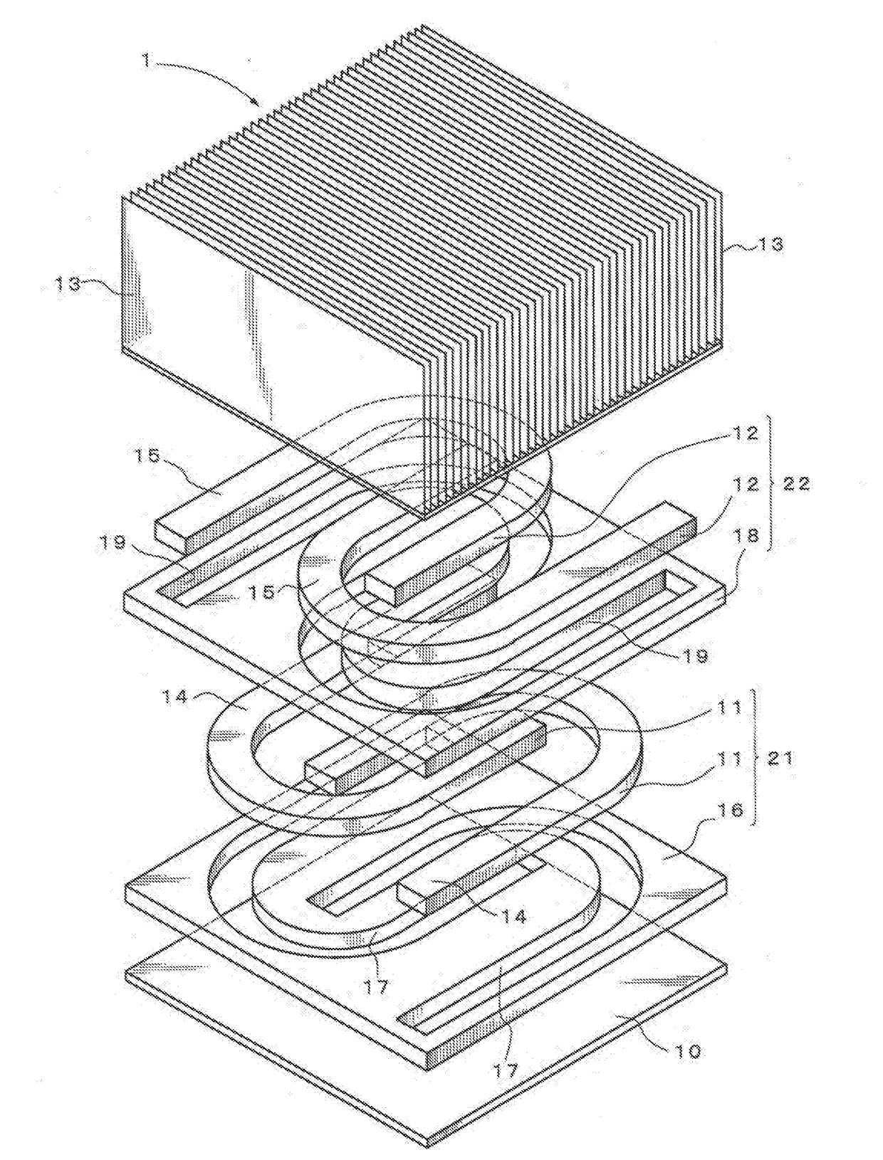
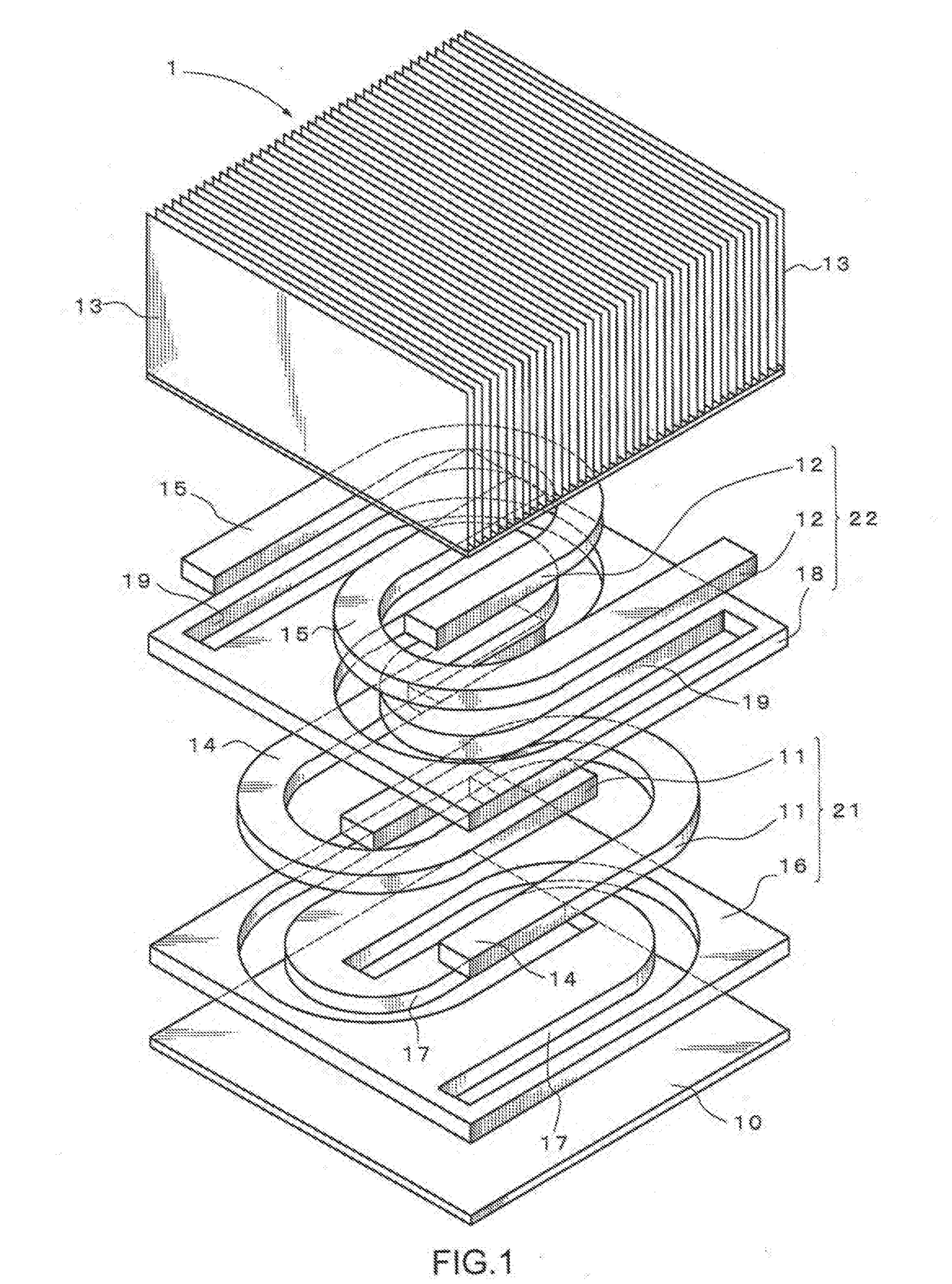
[0067]In the heat sink 1 according to the first embodiment, the arrangement of the second heat pipe 12 of the second heat pipe layer 22 in plan view was in an aspect in which the arrangement of the first heat pipe 11 of the first heat pipe layer 21 is reversed. Instead of this, as Example 1, as shown in FIG. 5, a heat sink 5 was used in an aspect in which an arrangement of the second heat pipes 12 of the second heat pipe layer 22 in plan view was such that the arrangement or the first heat pipes 11 of the first heat pipe layer 21 in plan view was rotated by 90° about the orthogonal axis to the surface of the heat receiving plate as the rotation axis.

[0068]As a comparative example 1, as shown in FIG. 6, of the heat sink 1 according to the first embodiment, a heat sink 6 not provided with a second heat p...


PUM


Abstract

Provided is a heat sink having excellent heat dissipation efficiency by having excellent thermal diffusion characteristics in a planar direction of a heat receiving plate. The heat sink has the heat receiving plate that is thermally connected to a heating element, heat pipes that are thermally connected to the heat receiving plate and are formed from a tube body, and heat dissipation fins that are thermally connected to the heat receiving plate, wherein the heat pipes are provided in a plurality of layers in a vertical direction to a surface of the heat receiving plate, and in at least two layers of the plurality of layers, positions of the heat pipes on the surface of the heat receiving plate are not identical to each other.

Description

TECHNICAL FIELD[0001]The present disclosure relates to a heat sink for cooling a heating element, and particularly relates to a heat sink for cooling electronic parts mounted on mobile bodies such as railroad vehicles, aircraft, automobiles or the like and electronic devices.BACKGROUND ART[0002]As a conventional heat sink, a heat sink is widely used which includes a heat receiving plate, heat pipes of a tube body which are thermally connected to the heat receiving plate and extend for a predetermined length in the surface direction of the heat receiving plate,, and heat dissipation fins erected on the heat pipes.[0003]However, the heat sink above is in an aspect in which heat pipes are arranged in a single layer in a vertical direction to a surface of the heat receiving plate. In an aspect in which heat pipes are provided in a single layer, due to constraints on the bending of the heat pipes, constraints on the number of the heat pipes that can be arranged on a heat source and the l...

Claims


Application Information

Patent Timeline
Patent Type & Authority Applications(United States)
IPC IPC(8): F28D15/02F28F1/04F28F3/02
CPCF28D15/0233F28F1/045F28F3/02F28D2015/0216H05K7/2039H01L23/427F28D15/0275H01L23/3672
Inventor TOCHIGI, YASUYUKITSENG, HUNG WEICHU, KUANG YUMEGURO, MASAHIROKAWABATA, KENYA
Owner FURUKAWA ELECTRIC CO LTD
Why Eureka
Try Eureka