
Heat dissipation device

a heat dissipation device and heat pipe technology, which is applied in the direction of indirect heat exchangers, electrical apparatus construction details, lighting and heating apparatus, etc., can solve the problems of prone to disengagement of fins from each other, large thickness of fins, and inability to conduct heat from fins, etc., to achieve the effect of heat dissipation device efficiency and facilitate dissipation of heat from fins

Inactive Publication Date: 2005-01-20
HON HAI PRECISION IND CO LTD
View PDF25 Cites 2 Cited by
  • Summary
  • Abstract
  • Description
  • Claims
  • Application Information

AI Technical Summary

Benefits of technology

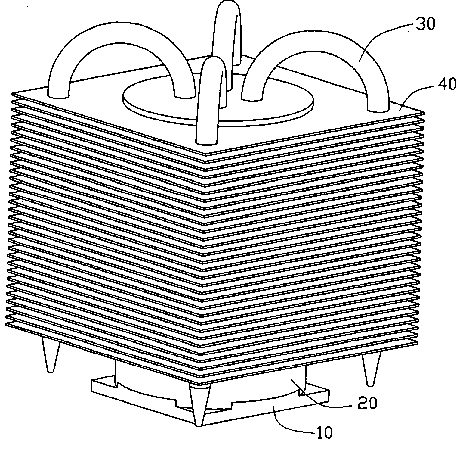
[0009] In order to achieve the object set out above, a heat dissipation device in accordance with a preferred embodiment of the present invention comprises a plurality of fins, a post and a plurality of heat pipes. Each fin defines an opening and a plurality of punctures spaced from the opening. The post is received in the openings of the fins. The heat pipes are engaged at opposite portions thereof with the post and the punctures of the fins. In the present invention, the post has a great thermal engaging area with the fins and is sufficiently engaged with the heat pipes. Apparently, the heat conducting efficiency of the heat dissipation device of the present invention is greater than that of a conventional heat dissipating device as disclosed in FIG. 3. Furthermore, the post is received in the openings of the fins and the heat pipes are engaged with the fins in the punctures spaced from the openings. Thus, the heat on the fins is evenly distributed. This facilitates to dissipate heat from the fins to ambient space.

Problems solved by technology

The fins are relatively thick in comparison with distances defined between each two adjacent fins, due to inherent limitations in extrusion technology.
Furthermore, a height of the fins is limited to about 13 times the distance between each two adjacent fins, also due to inherent limitations in extrusion technology.
The fins are prone to be disengaged from each other when the heat dissipation device is subjected to shock or vibration during transportation or in operation.
Part of or even the entire stack of fins may collapse.
With the continuing boom in electronics technology, numerous modern electronic components such as central processing units (CPUs) of computers can operate at very high speeds and thus generate large amounts of heat.
The heat must be efficiently removed from the CPU; otherwise, abnormal operation or damage may result.
The conventional heat removal way merely by conduct of heat is increasingly no longer able to adequately remove heat from these contemporary electronic components.
However, the engagement of the heat pipes with the base is limited by the thickness of the base.
Though the heat pipes inherently have a great heat-transfer capability, the heat dissipation device is not yet enhanced to remove heat from the CPU.

Method used


Image

  • Heat dissipation device
  • Heat dissipation device
  • Heat dissipation device

Examples


Embodiment Construction

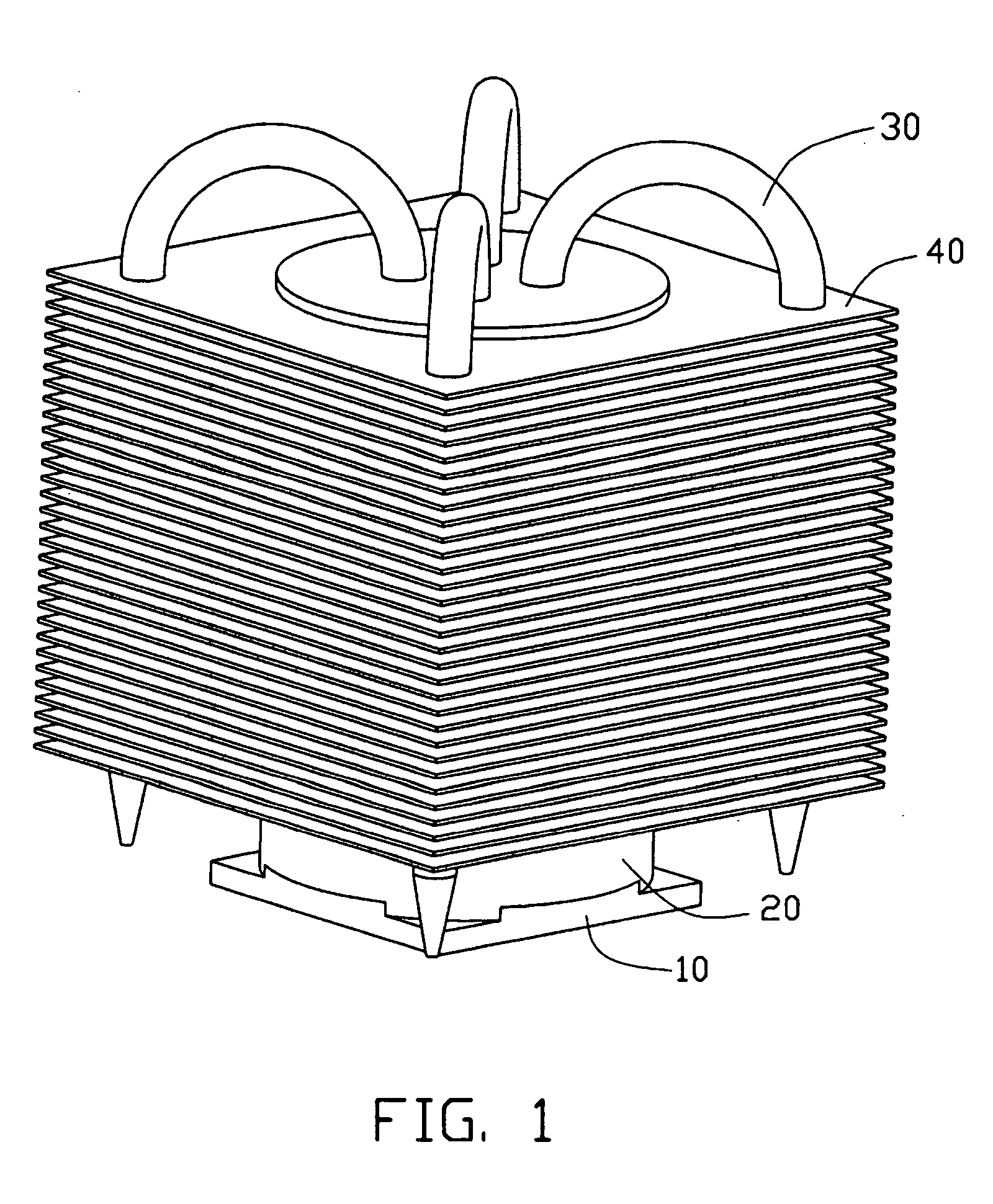
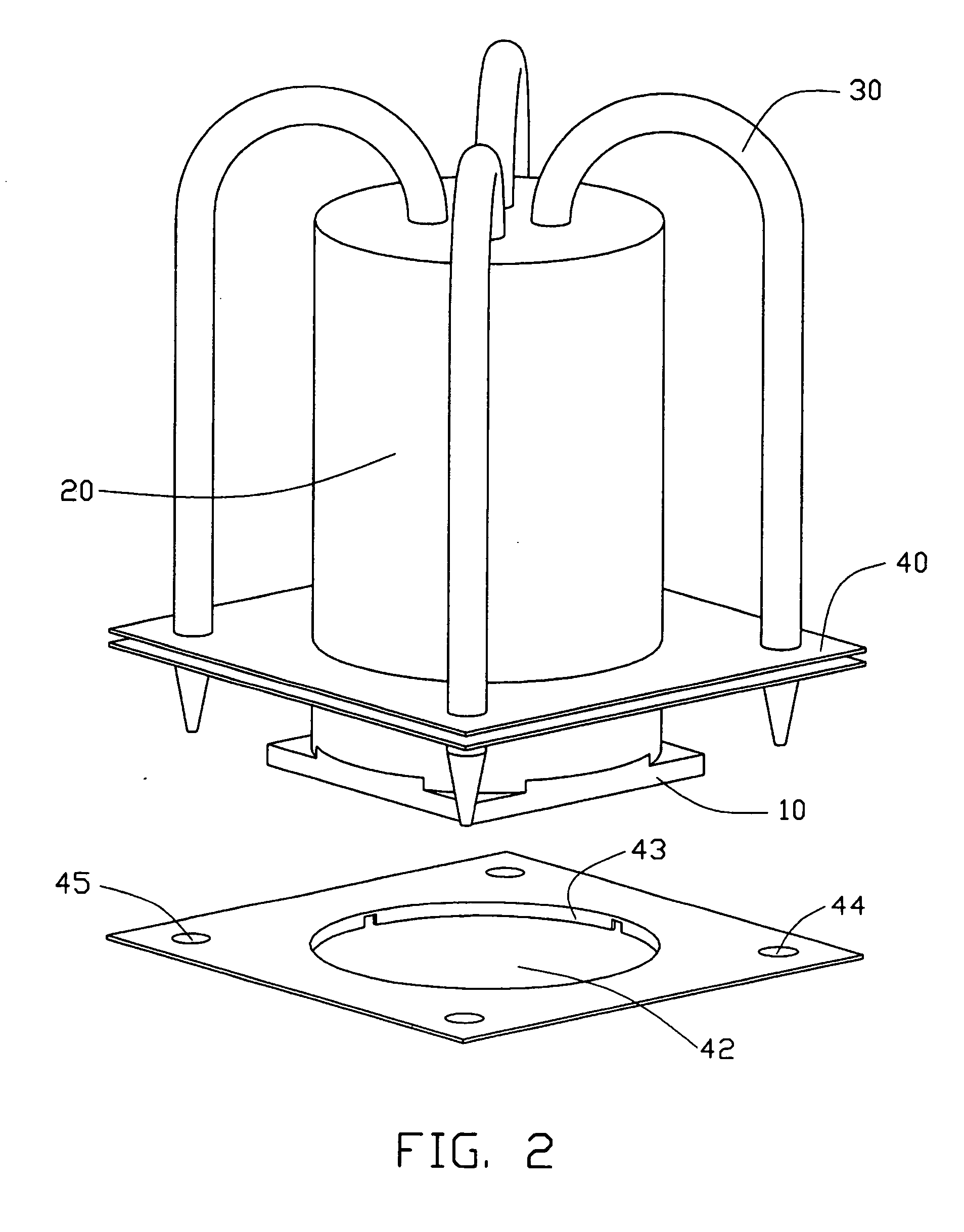
[0014] Referring to FIGS. 1-2, a heat dissipation device in accordance with the preferred embodiment of the present invention comprises a base 10, a post 20, a plurality of heat pipes 30 and a plurality of parallel fins 40.

[0015] The base 10 is for conducting heat from an electronic component (not shown) to be cooled. The post 20 is perpendicularly attached to the base 10 for removing heat therefrom. The post 20 defines a plurality of holes (not labeled). Each fin 40 defines a substantial central opening 42 for receiving the post 20, and a plurality of punctures 44 around and spaced from the opening 42. Each heat pipe 30 has a substantially inverted U-shaped configuration and is engaged at opposite portions thereof within the corresponding hole of the post 20 and the corresponding puncture 14 of each fin 40. Each fin 40 further forms a flange 43 at a periphery of the opening 42 for increasing thermal engaging area with the post 20 and a plurality of collars 45 around the punctures ...


PUM


Abstract

A heat dissipation device includes a plurality of fins (40), a post (20) and a plurality of heat pipes (30). Each fin defines an opening (42) and a plurality of punctures (44) spaced from the opening. The post is received in the openings of the fins. The heat pipes are engaged at opposite portions thereof with the post and the punctures of the fins.

Description

BACKGROUND OF THE INVENTION [0001] 1. Field of the Invention [0002] The present invention relates to heat dissipation devices for removing heat from electronic components, and more particularly to a heat pipe type heat dissipation device. [0003] 2. Description of Related Art [0004] Conventional heat dissipation devices used for removing heat from electronic components are mostly formed by extrusion of metallic material. Such kind of heat dissipation device commonly comprises a base, and a plurality of fins integrally extending from the base. The fins are relatively thick in comparison with distances defined between each two adjacent fins, due to inherent limitations in extrusion technology. This restricts the number of the fins that can be formed, and a total heat dissipation area that can be provided by the fins. Furthermore, a height of the fins is limited to about 13 times the distance between each two adjacent fins, also due to inherent limitations in extrusion technology. [0005...

Claims


Application Information

Patent Timeline
Patent Type & Authority Applications(United States)
IPC IPC(8): H01L23/427
CPCH01L23/427H01L2924/0002H01L2924/00
Inventor CHEN, CHUN-CHIFU, MENG
Owner HON HAI PRECISION IND CO LTD
Learn More