Substrate processing apparatus and method for processing substrate

Active Publication Date: 2018-10-04
ASM IP HLDG BV
View PDF2 Cites 232 Cited by
  • Summary
  • Abstract
  • Description
  • Claims
  • Application Information

AI Technical Summary

Problems solved by technology

This results in a problem that it is not possible to perform uniform plasma processing on the entire surface of the substrate.
For example, film f

Method used


Image

  • Substrate processing apparatus and method for processing substrate
  • Substrate processing apparatus and method for processing substrate
  • Substrate processing apparatus and method for processing substrate

Examples


Embodiment Construction

[0021]A shower plate, a substrate processing apparatus and a method for processing a substrate will be described with reference to the accompanying drawings. The same or corresponding components will be assigned the same reference numerals and duplicate description may be omitted.

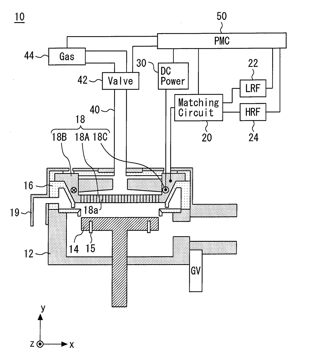
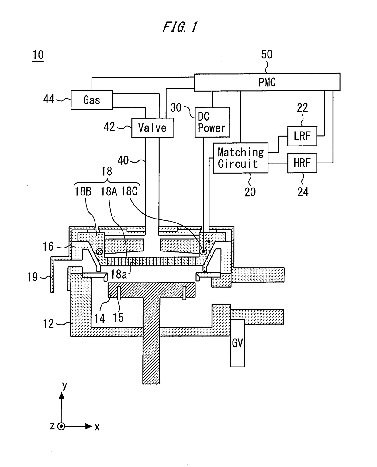
[0022]FIG. 1 is a cross-sectional view of a substrate processing apparatus 10. The substrate processing apparatus 10 is a parallel planar plasma processing apparatus. The substrate processing apparatus 10 is provided with a chamber 12. The chamber 12 is called a “reactor chamber.” A susceptor 14 is provided in the chamber 12. The susceptor 14 is a part on which a substrate is mounted. In some examples, a resistance heating apparatus is embedded in the susceptor 14. The susceptor 14 may be electrically grounded. The susceptor 14 is provided with susceptor pins 15 protruding from the susceptor 14 or housed in the susceptor 14 so as to be used to lift / lower the substrate.

[0023]An exhaust duct 16 formed of, for...


PUM

PropertyMeasurementUnit
Temperatureaaaaaaaaaa
Lengthaaaaaaaaaa
Currentaaaaaaaaaa

Abstract

A substrate processing apparatus includes a chamber, a susceptor provided in the chamber, a shower plate having a plate part provided with a plurality of through holes and formed of a conductor, a ring-shaped part connected to an outer edge of the plate part, surrounding the plate part and formed of a conductor and a lead wire embedded in the ring-shaped part and surrounding the plate part and the susceptor in plan view, the shower plate being provided so as to face the susceptor in the chamber, and a DC power supply that supplies a direct current to the lead wire.

Description

BACKGROUNDField[0001]Examples are described which relate to a substrate processing apparatus and a method for processing the substrate.Background Art[0002]JP2009-152603 discloses a plasma CVD apparatus having a cleaning function has an improved shower plate with holes having a uniform cross-sectional area to yield a high cleaning rate. The shower plate may serve as an electrode, and may have an electrically conductive extension connected to a power source. The shower plate, through which both cleaning gas and reaction source gas flow, may include a hole machined surface area with a size different than conventionally used to ensure a good film thickness uniformity during a deposition process. The size of the hole machined surface area may vary based on the size of a substrate to be processed, or the size of the entire surface of the shower plate.[0003]JP2016-122654 discloses a method and an apparatus for plasma processing of substrates. In this disclosure, a processing chamber has a ...

Claims


Application Information

Patent Timeline
IPC IPC(8): H01J37/32
CPCH01J37/32541H01J37/3244H01J37/32082H01J37/32697H01L21/67017H01L21/683H01L21/68721H01J37/32174H01L21/02274C23C16/45536
Inventor SUSA, YOSHIO
Owner ASM IP HLDG BV
Why Eureka
Try Eureka