

Medical system including medical imaging device and robotic bed
a robotic bed and medical imaging technology, applied in the field of medical systems, can solve the problems of not being able to develop a hospital application with only a limited space, a large robot arm needs to be configured, etc., and achieve the effect of efficient and accurate hybrid surgery, efficient and accurate transportation of patients, and reducing costs
- Summary
- Abstract
- Description
- Claims
- Application Information
AI Technical Summary
Benefits of technology
Problems solved by technology
Method used
Image

Examples
first example configuration
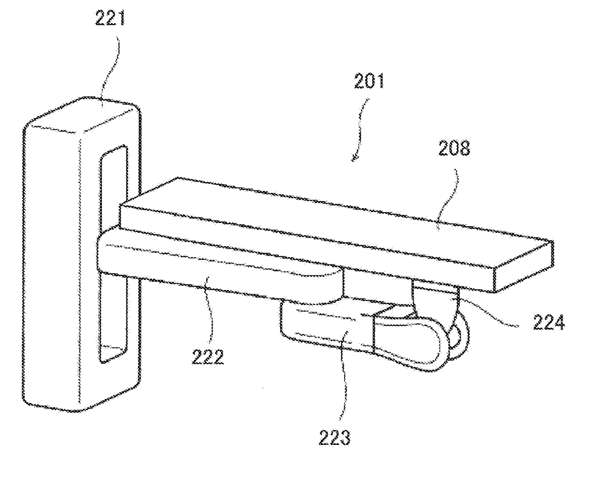
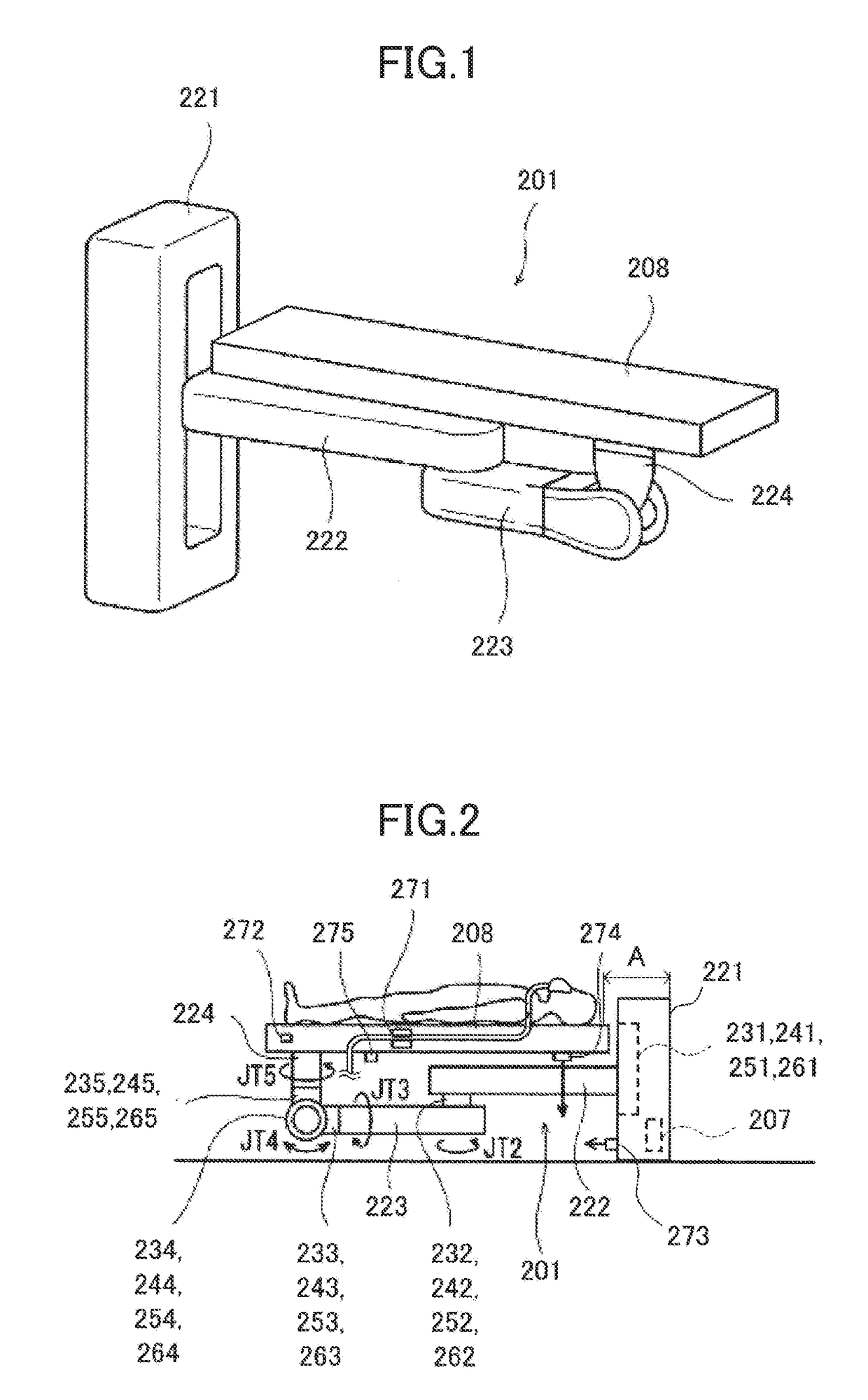
[0064]FIG. 1 is a diagram illustrating a perspective view, and FIG. 2 is a diagram illustrating a side view, of a robotic bed according to a first example configuration of one or more embodiments. A robot arm 201 used for the robotic bed has multiple degrees of freedom (i.e., three or more degrees of freedom), and has a distal end supporting a table 208 on which a target is placed. The table 208 and the robot arm 201 form the robotic bed.
[0065]As illustrated in FIG. 2, the robot arm 201 includes a base 221, a plurality of movable elements (first to third movable elements 222 to 224 in the present example configuration), and a plurality of joints (first to fifth joints 231 to 235 in the present example configuration).
[0066]The base 221 and one end portion of the first movable element 222 are coupled together by the first joint 231 traveling vertically straight, which enables the first movable element 222 to move in a first axial direction (i.e., in a vertical direction). The other en...
second example configuration
[0091]FIG. 9 is a diagram illustrating a perspective view, and FIG. 10 is a diagram illustrating a side view, of a robotic bed according to a second example configuration of the one or more embodiments. A robot arm 1001 used for the robotic bed has multiple degrees of freedom (i.e., three or more degrees of freedom), and has a distal end supporting a table 1008 on which a target is placed. The table 1008 and the robot arm 1001 form the robotic bed.
[0092]As illustrated in FIG. 10, the robot arm 1001 includes a base 1021, a plurality of movable elements (first to fourth movable elements 1022 to 1025 in the present example configuration), and a plurality of joints (first to sixth joints 1031 to 1036 in the present example configuration).
[0093]The base 1021 and one end portion of the first movable element 1022 are coupled together by a first joint 1031 traveling vertically straight, which enables the first movable element 1022 to move in a first axial direction (i.e., a vertical directi...
third example configuration
[0114]FIG. 15 is a diagram illustrating a side view of a robotic bed according to a third example configuration of one or more embodiments. A robot arm 1501 used for the robotic bed has multiple degrees of freedom (i.e., three or more degrees of freedom), and has a distal end supporting a table 1508 on which a target is placed. The table 1508 and the robot arm 1501 form the robotic bed.
[0115]As illustrated in FIG. 15, the robot arm 1501 includes a base 1521, a plurality of movable elements (first to third movable elements 1522 to 1524 in the present example configuration), and a plurality of joints (first to fifth joints 1531 to 1535 in the present example configuration).
[0116]The base 1521 and one end portion of the first movable element 1522 are coupled together by the first joint 1531 traveling vertically straight, which enables the first movable element 1522 to move in a first axial direction (i.e., in a vertical direction). The other end portion of the first movable element 152...
PUM
 Abstract
Description
Claims
Application Information