
Aircraft flight control system

Active Publication Date: 2018-10-11
AIRBUS OPERATIONS SAS
View PDF27 Cites 5 Cited by
  • Summary
  • Abstract
  • Description
  • Claims
  • Application Information

AI Technical Summary

Benefits of technology

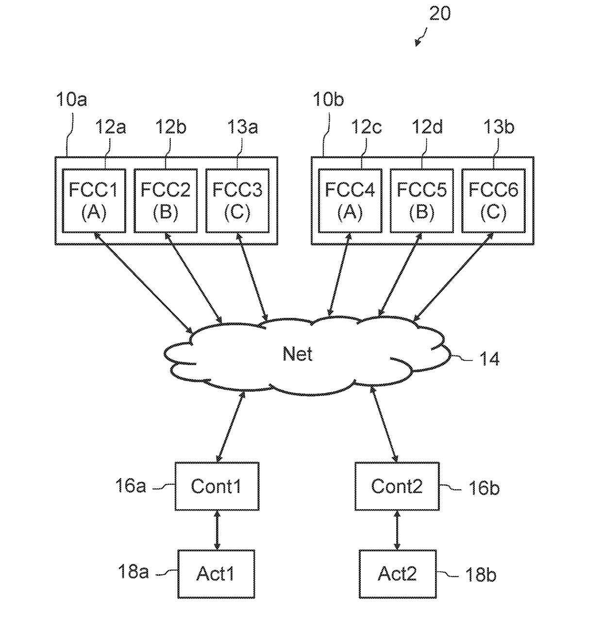
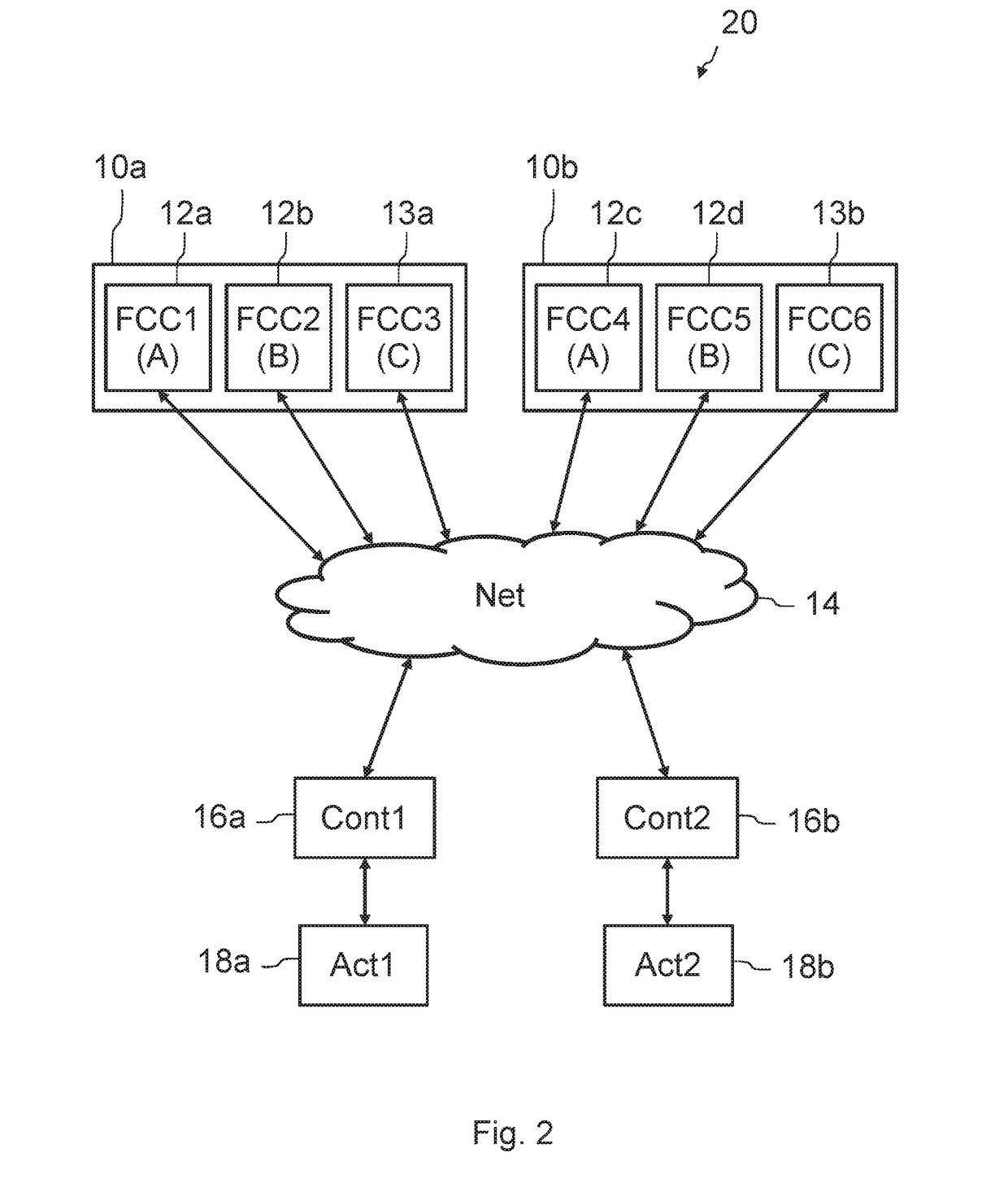
The patent describes a system for sharing information between different computers in an aircraft control system. These computers exchange data about important parameters that affect the flight, like airspeed or altitude. The system uses an algorithm to get a single, accurate value for each parameter based on the information from each computer. This value is then used by all the computers in the system for calculations about the flight trajectory. This approach reduces the workload for each computer and allows for more efficient decision-making.

Problems solved by technology

The flight control computers are dissimilar and redundant in such a way that the flight control system is robust to faults that may affect certain computers.
This gives rise to a very expensive computational overload since it makes it necessary to increase the computational capacities of the primary computers.

Method used


Image

  • Aircraft flight control system
  • Aircraft flight control system
  • Aircraft flight control system

Examples


first embodiment

[0037]In a first embodiment, the at least one flight parameter of the aircraft is a parameter of Boolean type such that a change of the consolidated value of the at least one flight parameter of the aircraft corresponds to a transition of the flight order computation law. This flight parameter corresponds, for example, to a flight phase of the aircraft (such as rolling on the ground, takeoff, climb flight, cruising flight, descent flight, landing, etc.). During the landing, a flight parameter of Boolean type corresponds, for example, to a condition of engagement of a piloting law making it possible to fly a flare phase of the trajectory of the aircraft. A switch from a value FALSE to a value TRUE of the flight parameter corresponds to a transition of the flight order computation law, from a law of descent to the landing runway, to the law making it possible to fly a flare phase.

[0038]In an advantageous manner, the common consolidation algorithm used by the primary computers to deter...

second embodiment

[0048]In a second embodiment, the at least one flight parameter of the aircraft is a parameter of numerical type, for example a speed of the aircraft, an altitude of the aircraft, etc. Each of the primary computers 12a, 12b, 12c, 12d determines a consolidated value of the at least one flight parameter. In an exemplary embodiment, the algorithm used by a primary computer to determine this consolidated value is the following:[0049]if 4 values of the at least one flight parameter that arise from the various computers are available for this computer, then the consolidated value corresponds to the second, in increasing order, of the 4 values;[0050]if 3 values of the at least one flight parameter that arise from the various computers are available for this computer, then the consolidated value corresponds to the median value of the 3 values;[0051]if 2 values of the at least one flight parameter that arise from the various computers are available for this computer, then the consolidated va...

third embodiment

[0054]In a third embodiment, the at least one flight parameter of the aircraft is a parameter of numerical type representative of a mode of operation of an automatic pilot of the aircraft. This parameter of numerical type is able to take a finite number of predetermined values each associated with a mode of operation of the automatic pilot of the aircraft. The current mode of operation of the automatic pilot corresponds in particular to a mode termed “engaged” of the automatic pilot, whose value is for example provided by an FCU (“Flight Control Unit”) system of the cockpit of the aircraft.

[0055]In an advantageous manner, the common consolidation algorithm used by the primary computers to determine the consolidated value of the at least one flight parameter determines a consolidated value of the at least one flight parameter corresponding to a value predominantly present among the values of the at least one flight parameter originating from the various primary computers, if this val...


PUM


Abstract

An aircraft flight control system comprises a set of primary computers, each configured to compute a flight order dependent on at least one aircraft flight parameter and intended for an aircraft control surface actuator remote controller. Each computer participates in command mode within a first virtual command / monitor pair and in monitor mode within a second virtual command / monitor pair. Each computer determines a consolidated flight parameter value as a function of a flight parameter value acquired by this computer and of flight parameter values received from the other computers, using a consolidation algorithm commonly used by all primary computers to each determine a consolidated flight parameter value, and compute the intended flight order for the remote controller as a function of the consolidated flight parameter value, according to a unique computation whose result is used by the computer both when acting in command mode and when acting in monitor mode.

Description

CROSS-REFERENCES TO RELATED APPLICATIONS[0001]This application claims the benefit of the French patent application No. 1753040 filed on Apr. 7, 2017, the entire disclosures of which are incorporated herein by way of reference.BACKGROUND OF THE INVENTION[0002]The invention relates to a system of flight commands of an aircraft, designed to operate control surfaces of the aircraft. Modern aircraft, transport airplanes, comprise a set of flight control computers which compute orders, called flight orders in the subsequent description, that they transmit to controllers of actuators of control surfaces of the aircraft. These control surfaces are, for example, flaps or ailerons situated at the level of the wings of the aircraft, elevators situated, for example, on a tailplane at the rear of the aircraft, a rudder situated on the fin, etc. The flight control computers are dissimilar and redundant in such a way that the flight control system is robust to faults that may affect certain comput...

Claims


Application Information

Patent Timeline
IPC IPC(8): B64C13/18G05B19/02
CPCB64C13/18G05B19/02G05B19/04B64C13/50G05D1/0077
Inventor BROT, PATRICE
Owner AIRBUS OPERATIONS SAS
Learn More