System and Apparatus for Gaze Tracking

a technology of gaze tracking and system, applied in the field of system and apparatus for gaze tracking, can solve the problems of inability to symmetrically position the two sources, signal loss in background, and large recommendation size, and achieve the effect of low resolution and sufficient detail

Active Publication Date: 2018-10-18
MIRAMETRIX
View PDF8 Cites 2 Cited by
  • Summary
  • Abstract
  • Description
  • Claims
  • Application Information

AI Technical Summary

Benefits of technology

[0009]It is an object of the following to provide an apparatus capable of providing low resolution images that still contain sufficient detail to allow a gaze tracking system to use them. It is additionally an object of the present disclosure to define an apparatus with a minimal number of illumination sources necessary to ensure the desired eye components are detectable in said images.

Problems solved by technology

From extensive testing, this recommendation seems to be too large, likely due to the fact that photographers merely wish to remove red eye effect, rather than attempt to maximize the effect.
Note that this heuristic does not guarantee a bright pupil response, but is used to attempt to maximize the users for which a bright pupil response will be apparent throughout the operating range.
This situation presents two problem scenarios which need to be taken into account:The actual background the signal is consistently over is sufficiently high that the signal is lost in the background.The input signal is spread over enough pixels on the sensor that it is indistinguishable from its background.
In fact, given a fixed sensor resolution, it is not possible to symmetrically position the two sources and guarantee that a desired operating range can be met.
The main limitation that the design of FIG. 2A creates is one of flexibility: the module must be designed with the illumination source distance 206 defined by hilluminator,bp in order to guarantee the operating range.
However, doing so implies a significantly larger required sensor resolution or significantly smaller lens field-of-view (FOV) than what would be necessary with the other configurations.
Unfortunately, this doubles the number of illumination sources required for a particular apparatus, which may be unrealistic due to manufacturing costs.

Method used


Image

  • System and Apparatus for Gaze Tracking
  • System and Apparatus for Gaze Tracking
  • System and Apparatus for Gaze Tracking

Examples


Embodiment Construction

[0020]The feasibility of on-axis bright-pupil gaze tracking is dependent on having the provided on-axis bright-pupil system and the user environment meet a number of criteria:[0021]Minimum Viable Sensor Spatial Resolution,[0022]Illuminator Size / Positioning, and[0023]Image Quality.

Minimum Viable Sensor Spatial Resolution

[0024]A gaze tracking system relies on the ability to accurately extract particular image aspects of the eye, using these to estimate the user's point of gaze at any given instance of time. It is therefore essential that the sensor used meets minimal resolution constraints, such that it can distinguish said image aspects within a given scene throughout the full operating range.

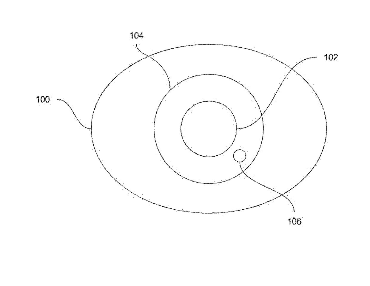
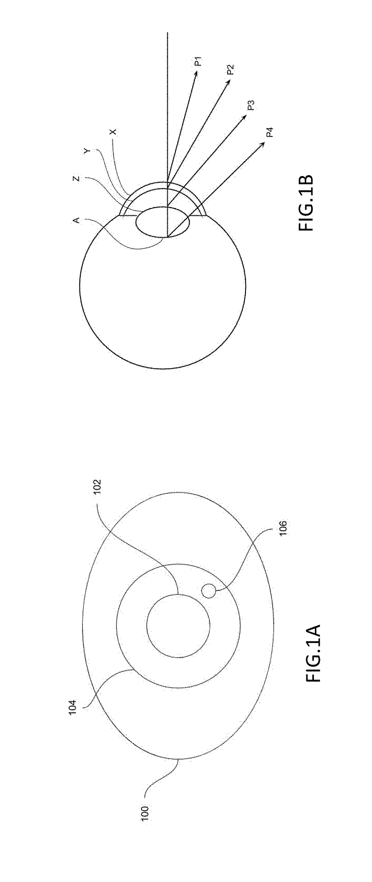
[0025]FIG. 1A demonstrates an eye 100, and a number of key components of it. Particularly, the pupil 102 is visible within the iris, bounded by the limbus 104, which defines the border between the corneal surface and the sclera. Within this region, {104∪102}, an illumination source creates a spe...


PUM


Abstract

A system and an apparatus are provided, for gaze tracking within a defined operating range. The apparatus includes at least one optical system, which capable of capturing radiation in a wavelength range produced by a composite illumination source. The apparatus also includes at least one set of illumination sources creating the composite illumination source, wherein: at least one of the illumination sources is positioned relative to the optical system such that it ensures a user bright pupil response at the beginning of the apparatus operating range; and the composite illumination source size is such that it creates a Purkinje image on a user's eye capable of being distinguished by the optical system at the end of the apparatus operating range. The apparatus also includes an illumination controller for activating and deactivating the at least one composite illumination source, and a signal processing controller for transmitting generated images from the at least one optical system.

Description

CROSS-REFERENCE TO RELATED APPLICATION(S)[0001]This application is a continuation of PCT Application No. PCT / CA2016 / 051550 filed on Dec. 30, 2016, which claims priority to U.S. Provisional Patent Application No. 62 / 273,681 filed on Dec. 31, 2015, both incorporated herein by reference.TECHNICAL FIELD[0002]The following relates to systems and apparatus for gaze tracking. More particularly to a minimal hardware complexity apparatus design and the gaze tracking systems incorporating same.DESCRIPTION OF THE RELATED ART[0003]The ability to remotely determine the gaze direction, albeit in a very constrained setting, was first reported in [1], in 1962. An apparatus for remote gaze tracking and pupillometry allowing the user to move freely within a 1 ft3 head box was disclosed in [2], in 1974. The two aforementioned apparatuses are limited in use, as research tools, given the constraints imposed on the user and their reduced portability.[0004]With the adoption of infrared illumination (refer...

Claims


Application Information

Patent Timeline
Patent Type & Authority Applications(United States)
IPC IPC(8): G06K9/00G06K9/20
CPCG06K9/00604G06K9/2027A61B3/113G06F3/013G06V40/19
Inventor ST-HILAIRE, SIMONSULLIVAN, NICHOLAS JOSEPH
Owner MIRAMETRIX
Why Eureka
Try Eureka