Multiple winding inductor assembly

Inactive Publication Date: 2018-10-18
MAG LAYERS SCI TECHNICS
View PDF7 Cites 2 Cited by
  • Summary
  • Abstract
  • Description
  • Claims
  • Application Information

AI Technical Summary

Benefits of technology

The present invention provides a multiple winding inductor assembly that reduces mutual inductance between different inductors and makes it easier to design and layout the circuit board. The inductor assembly can be extended in only one direction when adding more inductors, which simplifies the circuit design and layout. Overall, the invention helps to save energy and improve the efficiency of the circuit design.

Problems solved by technology

The SMD would also be more difficult, therefore leading to lower process speed and more complicated movement of fixtures or robotic arms.
As such, during the process of configuring the inductor assembly on the circuit board, the configuration accuracy becomes an issue (when the adaptability of fixtures and robotic arms is not taken into consideration).

Method used


Image

  • Multiple winding inductor assembly
  • Multiple winding inductor assembly
  • Multiple winding inductor assembly

Examples


Embodiment Construction

[0020]The following descriptions are exemplary embodiments only and are not intended to limit the scope, applicability or configuration of the invention in any way. Rather, the following description provides a convenient illustration for implementing exemplary embodiments of the invention. Various changes to the described embodiments may be made in the function and arrangement of the elements described without departing from the scope of the invention as set forth in the appended claims.

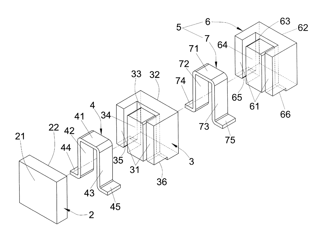
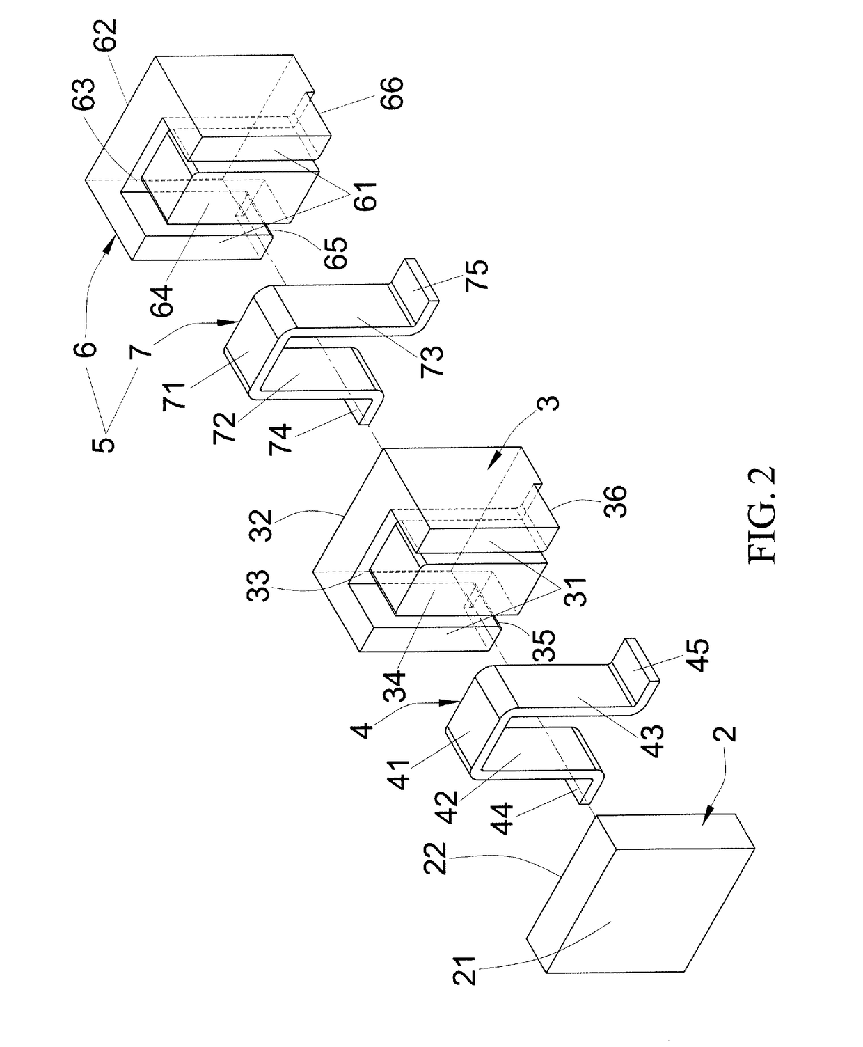
[0021]As shown in FIGS. 2 and 3, a multiple winding inductor assembly according to an embodiment of the present invention includes a first core piece 2, a second core piece 3, a first conductor 4, and a first core assembly 5.

[0022]The first core piece has a first major face 21 and a second major face 22. The second core piece 3 has a third major face 31 and a fourth major face 32. The second core piece 3 has a first indentation 33 on the third major face 31, and a first column 34 housed in the first ...


PUM


Abstract

The multiple winding inductor assembly includes a first core piece, a second core piece, a first conductor, and a first core assembly. The first core assembly includes a third core piece and a second conductor. The first and second conductors, together with the first, second, and third core pieces, form multiple inductors that, when working individually, do not cause mutual inductance on those not at work, thereby avoiding energy consumption. In addition, the inductor assembly may be extended in only one direction when cascading more inductors, facilitating circuit design and layout, and the configuration of the inductor assembly on the circuit board.

Description

BACKGROUND OF THE INVENTION(a) Technical Field of the Invention[0001]The present invention generally relates to inductors and, more particularly, to a multiple winding inductor assembly that may avoid mutual inductance and facilitate circuit design and layout.(b) Description of the Prior Art[0002]Inductors are commonly applied in electronic circuits for current choke, rectification, energy storage, oscillation, phase delay, or transformer. As electronic appliance are getting smaller with more functions, there are teachings about an inductor assembly having multiple windings functioning as multiple inductors. For example, R.O.C. Taiwan Patent No. M535865 teaches a mutual-inductance-free inductor assembly with multiple windings. As shown in FIG. 5 of M535865's drawings, the inductor includes a first piece, a second core piece, a middle piece, a first conductor, and a second conductor.[0003]FIG. 1 of the present disclosure is a perspective diagram showing the inductor assembly of M5358...

Claims


Application Information

Patent Timeline
IPC IPC(8): H01F27/29H01F37/00
CPCH01F37/005H01F27/29H01F3/14H01F17/04H01F17/043H01F27/263H01F27/292H01F27/38
Inventor YEH, HSIU-FACHEN, PIN-YULU, HANG-CHUNYANG, YA-WENCHANG, CHIEN-CHINHSU, YU-TINGLIANG, HUNG-CHIH
Owner MAG LAYERS SCI TECHNICS
Why Eureka
Try Eureka