Fuel control system

a technology of fuel control system and gas turbine engine, which is applied in the direction of turbine/propulsion fuel control, engine components, charge feed system, etc., can solve the problems of increased risk of incorrect activation, further adjustment of power threshold value, and inability to correctly activate logi

Inactive Publication Date: 2018-10-25
ROLLS ROYCE PLC
View PDF0 Cites 8 Cited by
  • Summary
  • Abstract
  • Description
  • Claims
  • Application Information

AI Technical Summary

Benefits of technology

[0018]The adjustments to the power threshold value are typically reversible. However, the control unit may prevent further adjustments to the power threshold value as a function of the measured rate of change of speed of the core engine spool when the determined power output exceeds the power threshold value. In this way adjustments (and particularly step change adjustments) can be latched when fuel flow upward runaway events are confirmed.

Problems solved by technology

However, there is a concern that this logic could be incorrectly activated if spurious torque spikes occur e.g. due to electrical interference.
However, reducing the torque threshold results in an increased risk of incorrect activation due to spurious torque spikes.
However, the control unit may prevent further adjustments to the power threshold value as a function of the measured rate of change of speed of the core engine spool when the determined power output exceeds the power threshold value.

Method used


Image

  • Fuel control system
  • Fuel control system
  • Fuel control system

Examples


Embodiment Construction

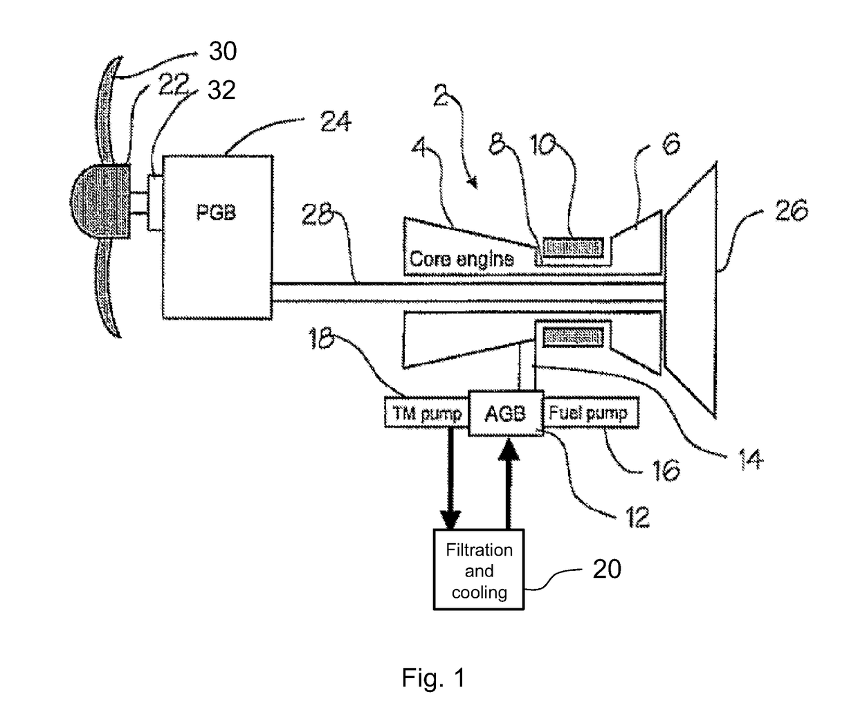
[0029]The propulsion unit shown in FIG. 1 comprises a core engine 2 comprising a high pressure compressor 4 and a high pressure turbine 6 which are interconnected by a high pressure shaft 8. A combustor 10 is situated between the compressor 4 and the turbine 6. An accessory gearbox 12 has an input driven from the shaft 8 by means of a radial power off-take shaft 14. Outputs of the accessory gearbox 12 drive various components, including a fuel pump 16 which provides a pressurised fuel supply for the combustor 10, and a turbomachinery lubricant pump 18 which supplies lubricant, such as oil, to various systems of the engine, including the accessory gearbox 12 and bearings of the shaft 8. Lubricant supplied by the lubricant pump 18 is filtered and cooled by a filtering and cooling system 20.

[0030]A propeller 22 is driven through a propeller gearbox 24 by means of a low pressure, free power turbine 26, which transmits power to the propeller gearbox 24 through a low pressure shaft 28 whi...


PUM


Abstract

A fuel control system is provided for a gas turbine engine having a core engine comprising at least one core engine spool in which a compressor and a turbine are interconnected by a shaft. The system includes a first engine sensor which determines a power output of the engine. The system further includes a control unit which is configured to compare the determined power output with a value of a power threshold, and to command a reduction in fuel supplied to the engine when the determined power output exceeds the power threshold value. The system further includes a second engine sensor which measures the rate of change of rotational speed of the core engine spool. The control unit is further configured to adjust the power threshold value as a function of the measured rate of change of speed of the core engine spool.

Description

CROSS-REFERENCE TO RELATED APPLICATION[0001]This application is based upon and claims the benefit of priority from British Patent Application Number 1706269.6 filed Apr. 20, 2017, the entire contents of which are incorporated by reference.BACKGROUNDField[0002]The present disclosure relates to a fuel control system for a gas turbine engine.Description of Related Art[0003]Fuel control systems for use in controlling the supply of fuel to an aircraft engine generally comprise a control unit, which may be part of the engine electronic controller (EEC), and a hydro-mechanical unit controlled by the control unit. For example, the hydro-mechanical unit may include a metering valve operable to control the rate at which pressurised fuel passes from a supply line to a delivery line. Typically, the hydro-mechanical unit also includes a pressure drop control arrangement (e.g. comprising a pressure drop control valve and an associated spill valve) which is operable to maintain a substantially con...

Claims


Application Information

Patent Timeline
Patent Type & Authority Applications(United States)
IPC IPC(8): F02C9/28F02C9/46
CPCF02C9/28F02C9/46F05D2220/323F05D2270/304F05D2270/335F02C7/232F05D2270/052F05D2270/09F05D2270/309
Inventor RENOLD-SMITH, WILLIAMHOROBIN, MARCUS S.
Owner ROLLS ROYCE PLC
Why Eureka
Try Eureka