Landing gear fairing with aerodynamic surfaces for tail sitter aircraft
- Summary
- Abstract
- Description
- Claims
- Application Information
AI Technical Summary
Benefits of technology
Problems solved by technology
Method used
Image


Examples
Embodiment Construction
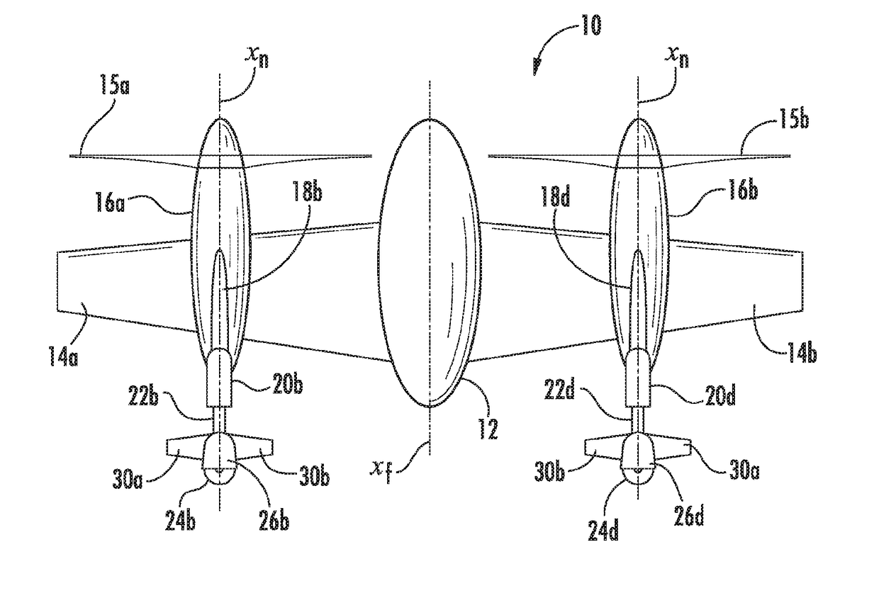
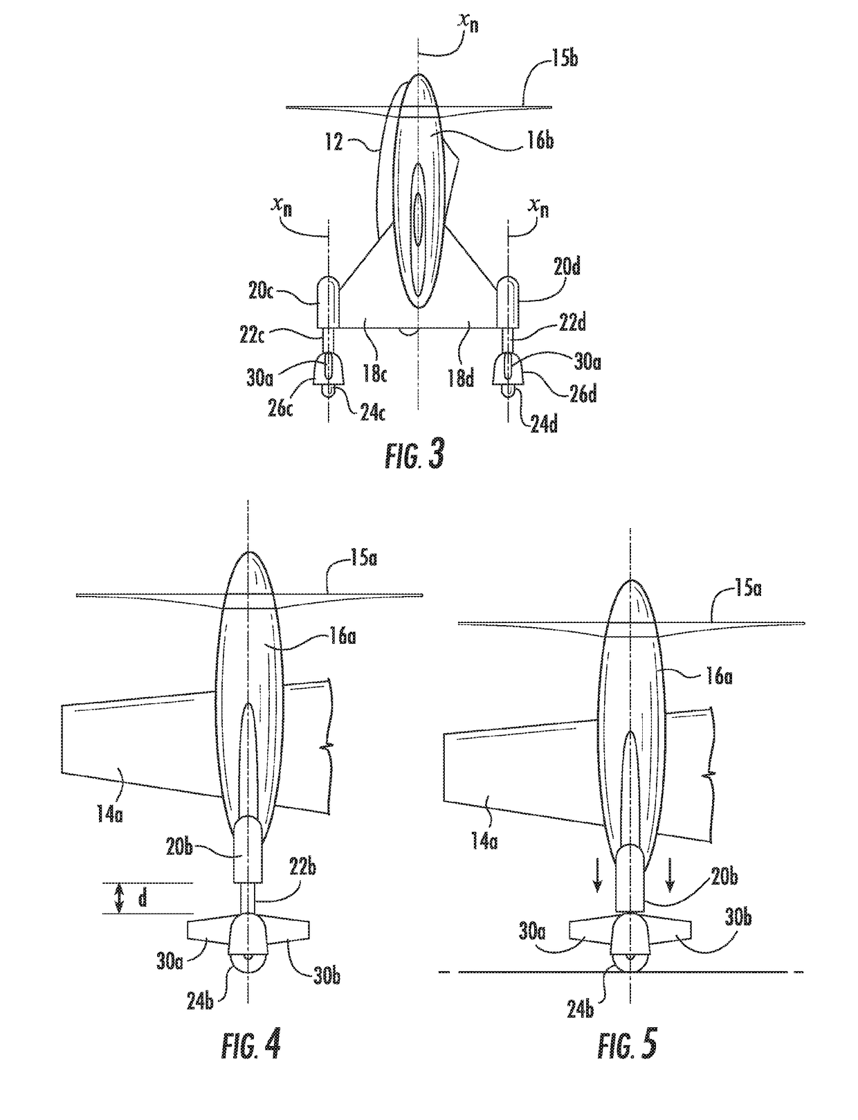
[0026]Referring now to the drawings, wherein like reference numerals identify similar structural features or aspects of the subject invention, there is illustrated in FIG. 1 a rotor blown wing tail sitter aircraft designated generally by reference numeral 10. The tail sitter aircraft 10 includes an elongated fuselage 12 defining a longitudinal fuselage axis Xf. As illustrated in FIGS. 1 through 3, the fuselage 12 of the aircraft 10 is in a horizontal orientation corresponding to a forward flight mode.
[0027]Referring to FIG. 1, a pair of laterally opposed horizontal main wings 14a and 14b extends radially outwardly from the fuselage 12, perpendicular to the fuselage axis Xf. Nacelles 16a and 16b are supported on main wings 14a and 14b, respectively. Each nacelle 16a, 16b defines a longitudinal nacelle axis Xn, extending parallel to the longitudinal axis Xf of fuselage 12. The nacelles 16a and 16b have respective propellers or rotors 15a and 15b operatively associated therewith.
[0028]...
PUM
 Abstract
Description
Claims
Application Information