Optical plug connector device

a technology of optical plugs and connectors, applied in the field of optical plug connector devices, can solve the problems of high component cost, inability to automate the insertion process, and high pressing force, and achieve the effects of reducing manufacturing precision, reducing manufacturing cost, and reducing manufacturing cos

Inactive Publication Date: 2018-11-01
REICHLE & DE-MASSARI
View PDF3 Cites 5 Cited by
  • Summary
  • Abstract
  • Description
  • Claims
  • Application Information

AI Technical Summary

Benefits of technology

[0010]Thanks to such a configuration, it is possible to provide an optical plug connector device having advantageous properties with regard to a manufacturing, in particular an automated manufacturing, and / or with regard to manufacturing costs. In particular, the first fiber holding element may be manufactured in greater numbers by means of an advantageously economical and / or simple mass production process, for example by means of an injection molding process, and / or be made from an economical material. The second fiber holding element, having a higher manufacturing precision than the first fiber holding element, can be manufactured in particular in numbers advantageously adapted to needs and in a different manufacturing process. Moreover, an advantageously simple and in particular automated inserting of optical fibers into fiber holding elements can be made possible with high manufacturing quality.
[0026]Furthermore, a method for manufacturing an optical plug connector device with at least one lens array and with at least one fiber holder is proposed, which has at least one first fiber holding element and at least one second fiber holding element having a higher manufacturing precision than the first fiber holding element, wherein end regions of a plurality of optical fibers are positioned relative to the lens array by means of the fiber holder. In this way, an advantageously simple and / or economical manufacturing can be accomplished, which can be advantageously easily automated or at least partly automated.

Problems solved by technology

The making of the precision recesses is done with large manufacturing expense, resulting in high component costs.
Moreover, many optical fibers need to be inserted in the individual precision recesses during a manufacturing process, and this insertion process cannot be done by automation.
A further drawback of the known MPO and MTP ferrules is the need for high pressing forces, which increase with the number of optical fibers.

Method used


Image

  • Optical plug connector device
  • Optical plug connector device
  • Optical plug connector device

Examples


Embodiment Construction

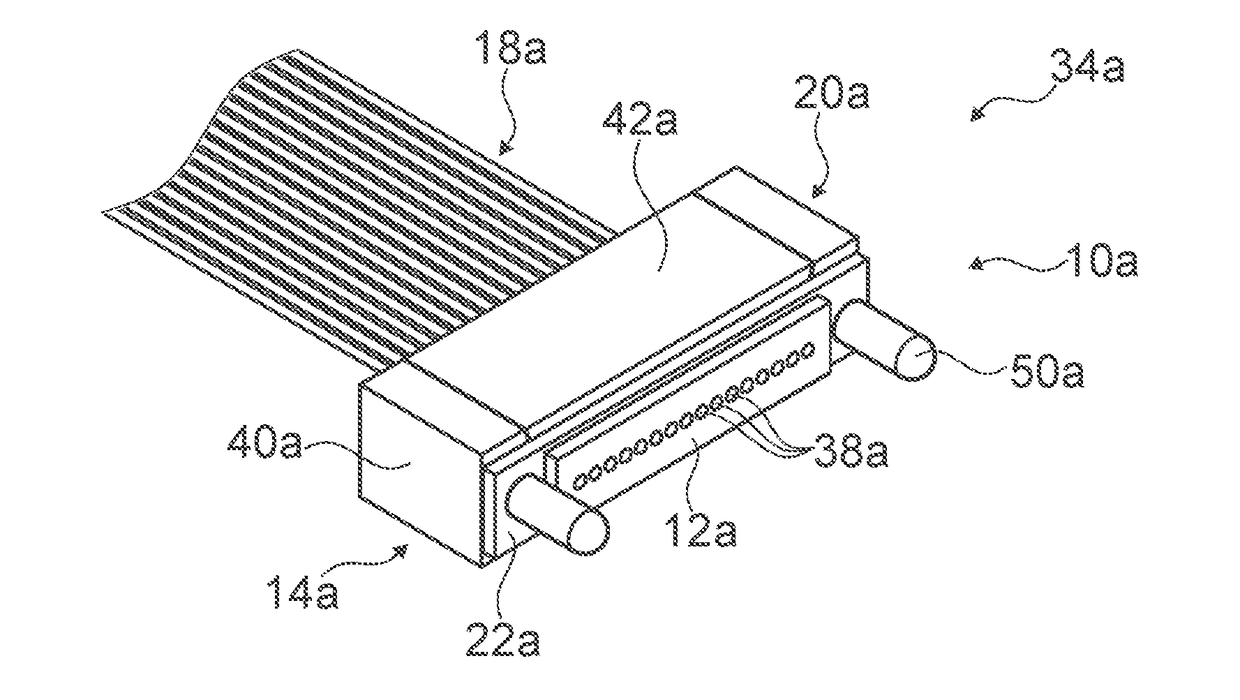
[0043]FIG. 1 shows a configured optical cable 34a, in particular an optical patch cable. The optical cable 34a comprises an optical plug connector device 10a and a plurality of optical fibers 18a. The optical plug connector device 10a has a lens array 12a. The lens array 12a comprises a plurality of optical lens elements 38a. The number of lens elements 38a of the lens array 12a corresponds to the number of optical fibers 18a. Alternatively, the number of lens elements may differ from the number of optical fibers and in particular be greater than the number of optical fibers. Moreover, the optical plug connector device 10a has a fiber holder 14a. The fiber holder 14a is designed to position end regions 16a (not visible in FIG. 1) of the optical fibers 18a relative to the lens array 12a. The fiber holder 14a and the lens array 12a are produced as separate components. Between the lens array 12a and the fiber holder 14a there is arranged an index adjustment material, in particular an i...


PUM


Abstract

An optical plug connector device includes at least one lens array and at least one fiber holder, which is designed to position end regions of a plurality of optical fibers relative to the lens array, and which has at least one first fiber holding element wherein the fiber holder comprises at least one second fiber holding element having a higher manufacturing precision than the first fiber holding element.

Description

PRIOR ART[0001]The invention relates to an optical plug connector device according to Claim 1.[0002]From US 2012 / 0093462 A1 there is known a multi-fiber plug, which comprises a ferrule and a lens array fashioned as a single piece with the ferrule. Conical channels are devised in the ferrule, which are designed to receive an optical fiber each and to orient the optical fibers relative to the lens array.[0003]Moreover, MPO and MTP ferrules are known in the prior art, in which an orienting of optical fibers is done by means of precision recesses. The making of the precision recesses is done with large manufacturing expense, resulting in high component costs. A play between the precision recesses and optical fibers arranged in the precision recesses cannot be avoided. Moreover, many optical fibers need to be inserted in the individual precision recesses during a manufacturing process, and this insertion process cannot be done by automation. A further drawback of the known MPO and MTP fe...

Claims


Application Information

Patent Timeline
Patent Type & Authority Applications(United States)
IPC IPC(8): G02B6/38
CPCG02B6/3839G02B6/3853G02B6/3885G02B6/382G02B6/3858G02B6/32G02B6/3834
Inventor GSELL, CHRISTIANROSE, ANDREASRUIZ, BLANCAEGGIMANN, FABIANHERR, GUNTERCERNA, VERENA
Owner REICHLE & DE-MASSARI
Why Eureka
Try Eureka