Girder element for concrete formwork comprising a structure for automatically compensating bending strains

a technology of girder and concrete, which is applied in the direction of form/shutter/falsework, shaping building parts, walls, etc., can solve the problems of unsatisfactory solid structure for supporting or fastening a girder construction, unsatisfactory concrete structure to be manufactured, and unsatisfactory bending strains of the manufactured concrete structure,

Inactive Publication Date: 2010-05-13
PERI GMBH
View PDF3 Cites 10 Cited by
  • Summary
  • Abstract
  • Description
  • Claims
  • Application Information

AI Technical Summary

Benefits of technology

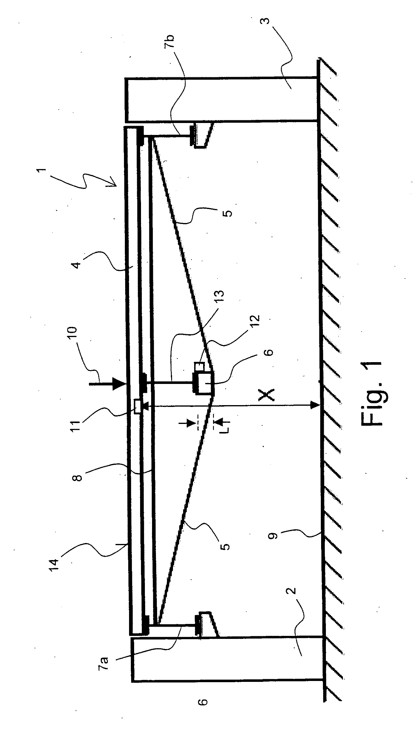
[0015]A desired shape of the girder of the girder element can be maintained at fundamentally arbitrary loads by setting the shape of the girder using a measuring and regulation system. Prior calculations of the load are not necessary (within a maximum strain of the girder element). The girder element does not have to be particularly rigid as a whole, because a deformation of the girder is prevented by the length-adjustable compensation device. The girder element according to the invention can thus be relatively light and have little material, whereby it is easy to handle during the construction and teardown of formwork. In comparison to typical girder elements, weight reductions of up to 50% may be achieved.
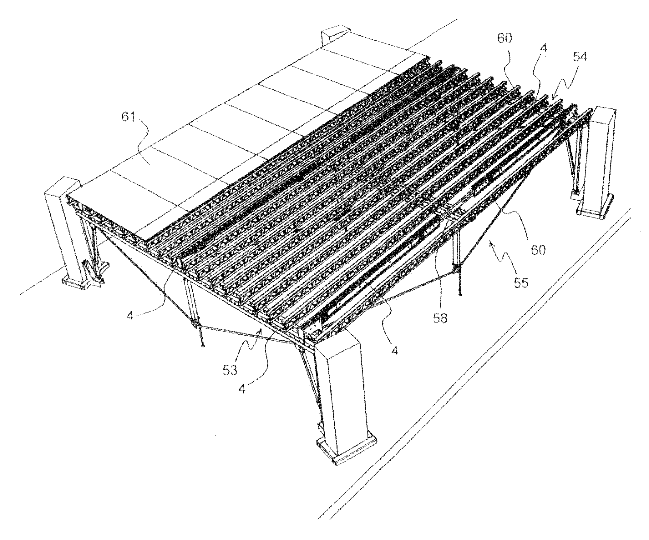
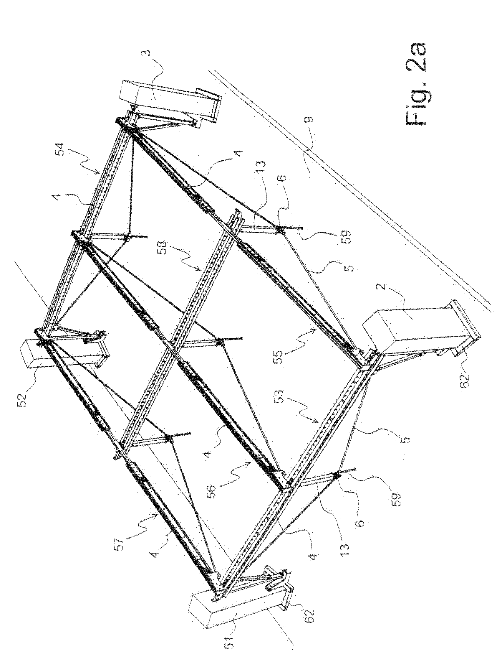
[0029]The use of girder elements according to the invention for constructing concrete formwork, in particular for implementing ceiling formwork, is also within the context of the present invention. This concrete formwork has a high manufacturing precision and, in particular, can be used free of formwork deformation. Because girder elements of lighter construction may be used universally, the construction and teardown of the formwork according to the invention requires little work and is thus cost-effective.

Problems solved by technology

Deformed girder structures fundamentally result in undesired dimensional deviations of the manufactured concrete structure from the desired concrete structure.
However, a high density of support points is associated with a high outlay for work and material during construction of the formwork.
Furthermore, adequately solid structures for supporting or fastening a girder construction are simply not available to a sufficient extent for many concrete structures to be manufactured.
These known girder elements are very rigid, but are very heavy and are therefore difficult to handle on the construction site and are expensive to produce because of the large steel consumption.
However, prior calculation of the bending deformation is time-consuming and difficult and must be performed for each concrete structure to be manufactured and also individually and newly for each girder element.
A specially prepared girder element is typically only usable for a single concrete structure to be manufactured at a specific point of the girder construction.
Furthermore, maintaining the desired ceiling thickness is difficult, because the formwork sag changes during the concrete casting procedure.

Method used


Image

  • Girder element for concrete formwork comprising a structure for automatically compensating bending strains
  • Girder element for concrete formwork comprising a structure for automatically compensating bending strains
  • Girder element for concrete formwork comprising a structure for automatically compensating bending strains

Examples


Embodiment Construction

[0019]In a preferred embodiment of the girder element according to the invention, the motorized drive comprises an electric drive, in particular a linear motor. Such a drive is simple and easy to maintain.

[0020]In an alternative embodiment, which is also preferred, the motorized drive comprises a hydraulic drive or a pneumatic drive. Particularly large forces may be applied using a hydraulic drive. Water and oil can preferably by used as hydraulic media. Water does not cause any damage on the construction site in the event of leaks. Typical high-pressure cleaning devices (and / or the assemblies thereof) can be used for providing and maintaining pressure with water because of the slow pace of deformation pathways during concrete casting. A joint provision of pressure for a plurality of compensation devices, in particular also of various girder elements, can be performed with hydraulic or pneumatic drives; the force regulation at the individual compensation devices is performed by loca...


PUM


Abstract

A girder element (1; 21; 31; 41; 53-57) for concrete formwork comprises a girder (4) for receiving external forces (10), a tension rod (5) extending behind the girder (4) and at least one lengthwise adjustable tensioning device that is interposed between the girder (4) and the tie rod (5), the local distance between the girder (4) and the tie rod (5) being adjustable by means of said tensioning device. The invention is characterized in that the lengthwise adjustable tensioning device is configured as a lengthwise adjustable compensation device (6; 6a, 6b) which is motor driven to adjust the length of the compensation device (6; 6a, 6b). A measuring device is used to determine the position (x) of the girder (4) in the area of the compensation device (6; 6a, 6b) relative to a desired position (xs). A control device (12) is used to adjust the length (L) of the compensation device (6; 6a, 6b) depending on the position (x) of the girder (4). The girder element permits precise and cost-effective manufacture of any concrete structures.

Description

[0001]The invention relates to a girder element for a concrete formwork, in particular a ceiling girder element, having a girder for accepting external forces, a traction band, which runs behind the girder, and at least one length-adjustable tensioning device, which is situated between the girder and traction band, using which the local spacing between the girder and traction band is settable.[0002]Such a girder element is known, for example, from the brochure “Column Hung System” of HI-LITE Systems, division of JASCO Sales Inc., Mississauga, Ontario, Canada, 2001.[0003]Formwork technology is frequently used for manufacturing buildings. A building structure to be manufactured, such as a wall, column, or ceiling, has formwork elements built around it (“erecting formwork”) and is filled with liquid concrete. The concrete is subsequently permitted to harden.[0004]The formwork elements, which have a formwork skin subjected directly to the liquid concrete, have a girder construction buil...

Claims


Application Information

Patent Timeline
Patent Type & Authority Applications(United States)
IPC IPC(8): E04G11/48
CPCE04C3/005E04G11/50E04G11/56
Inventor BRAUN, HANS
Owner PERI GMBH
Why Eureka
Try Eureka