Safety mechanism for a retaining needle and a retaining needle having the safety mechanism

a technology of safety mechanism and retaining needle, which is applied in the direction of infusion needles, catheters, infusion devices, etc., can solve the problems of high manufacturing cost, high manufacturing cost, and contaminated puncture needles, and achieves simple structure, high safety, and convenient retraction of puncture needles.

Active Publication Date: 2018-11-08
SOL MILLENNIUM MEDICAL LTD
View PDF2 Cites 1 Cited by
  • Summary
  • Abstract
  • Description
  • Claims
  • Application Information

AI Technical Summary

Benefits of technology

[0006]The present utility model provides a safety mechanism for a retaining needle and a retaining needle having the safety mechanism, which safety mechanism allows a safer retraction of the puncture needle after a catheter and a puncture needle of the retaining needle are correctly penetrated into the blood vessel, which avoids a user from contacting the used punctured needle again; therefore, it has a high safety, a simple structure, and cost-effectiveness.

Problems solved by technology

However, the blood-tainted puncture needle will bring many risks to the healthcare workers and other persons who possibly contact medical garbage, such as infection with diseases, etc.
Currently, puncture-proof retaining needles have emerged in markets, but most of them have a complex structure and a high manufacturing cost; therefore, the price is dear, while the operation is inconvenient.

Method used


Image

  • Safety mechanism for a retaining needle and a retaining needle having the safety mechanism
  • Safety mechanism for a retaining needle and a retaining needle having the safety mechanism
  • Safety mechanism for a retaining needle and a retaining needle having the safety mechanism

Examples


first embodiment

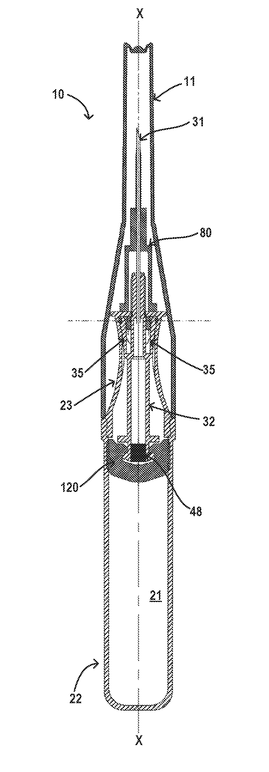
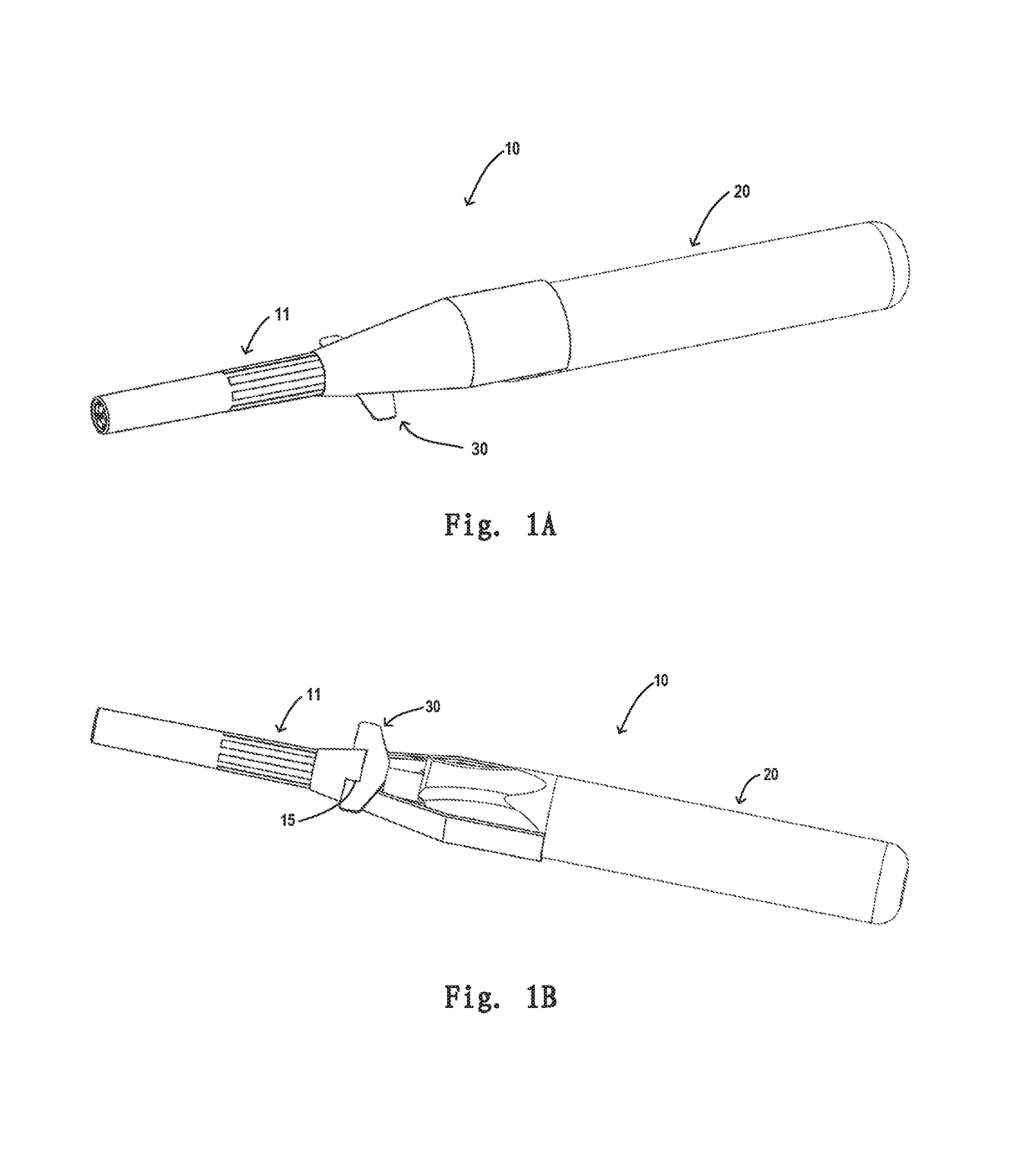
[0059]FIGS. 1A and 1B are stereoscopic diagrams of an unused retaining needle 10 observed from obliquely above and from obliquely down according to a first preferred embodiment of the present utility model. FIGS. 2A and 2B are longitudinally sectional views of the retaining needle 10 as illustrated in FIGS. 1A and 1B along different sections. The retaining needle 10 has a longitudinal axis X-X (as illustrated in FIGS. 2A and 2B). The retaining needle 10 comprises: a hollow handle 20; a needle and needle seat assembly 30 at least partially disposed within the handle 20; a catheter and catheter hub assembly 80 disposed at a distal side of the handle 20 and surrounding a part of the needle and the needle seat assembly 30; and a security mechanism 100. Preferably, the retaining needle 10 further comprises a protection sheath 11 disposed at a distal end of the retaining needle for preventing the unused retaining needle from puncturing a person in contact.

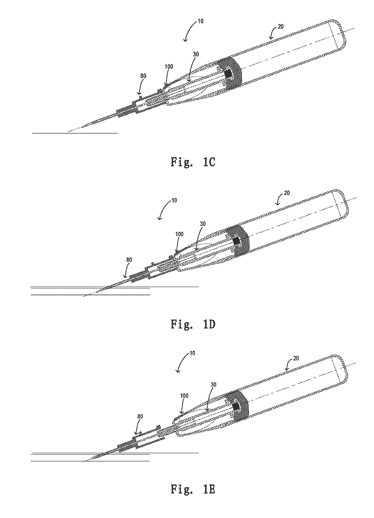
[0060]FIGS. 1C-1G illustrate a u...

second embodiment

[0075]FIGS. 13A, 13B, and 13C are stereoscopic views and sectional views of a protection sheath 11′ of the retaining needle 10′ as illustrated in FIGS. 11A and 11B. Similarly, the shape of the protection sheath 11′ is also substantially identical to the shape of a distal side portion of the retaining needle 10′ (or the distal side portion of the handle 20′ and the catheter and catheter hub assembly), and a lower side of the protection sheath 11′ has a portion to be removed so as to be sleeved to the distal side portion of the retaining needle 10′, and a notch 15′ is also reserved on the protection sheath 11′ so as to be snapped onto a wing 85′ of the catheter and catheter hub assembly 80′.

[0076]Hereinafter, the distal side portion of the handle of the retaining needle, the needle seat, and the button of the safety mechanism according to the second embodiment will be described specifically.

[0077]FIGS. 14A, 14B, 14C, and 14D are stereographic diagrams of the needle seat 32′ of the re...

third embodiment

[0087]Hereinafter, a distal side portion of a handle of a retaining needle, a snap sleeve of the handle, a needle seat, and a button of a safety mechanism will be described in detail.

[0088]FIGS. 22A, 22B, and 22C are stereoscopic diagrams of a needle seat 32″ of a retaining needle 10′ according to the third embodiment as illustrated in FIG. 20 and longitudinal sectional views sectioned from different sides. Similarly, the needle seat 32″ likewise has a substantially hollow column needle seat body, a diameter reduced portion 33″ is provided at a distal side of the needle seat body, and on the needle seat body is also provided an elastic arm 35″ spreading radially outwardly. One elastic arm 35″ is shown in the figures. However, those skilled in the art may understand that the number of elastic arms 35″ may be one or more than two, as long as they can cooperate with corresponding portions of the handle 20″; and the column of the needle seat body of the needle seat 32″ is preferably a ...


PUM


Abstract

The present utility model discloses a safety mechanism for a retaining needle and a retaining needle having the safety mechanism. The retaining needle comprises a hollow handle and a needle seat at least partially disposed within the handle for receiving a puncture needle, the safety mechanism comprises: a snapping step disposed at an inner side of the hollow handle; at least one elastic arm radially spreading outward disposed on the needle seat, an end portion of the elastic arm has a snapping portion radially protruding outward, the snapping portion being engaged with the snapping step; a button disposed on a distal side portion of the handle; the button, when being depressed, pushing the elastic arm along a radial inward direction, such that while the snapping portion of the elastic arm is disengaged from the snapping step, the needle seat and the puncture needle stretching outside of the handle are retracted into the hollow handle by virtue of vacuum within the hollow handle.

Description

FIELD OF THE INVENTION[0001]The present utility model relates to a safety mechanism for a retaining needle and a retaining needle having the safety mechanism.BACKGROUND OF THE INVENTION[0002]With the development of modern medicine, researchers have been devoted to reduce pains brought by medical treatments. Use of intravenous retaining needles (also referred to intravenous trocar) can reduce pains caused by repetitive venipuncture to patients and alleviate workload of healthcare workers, which currently has gained wide application. The existing retaining needles generally comprise a puncture needle and a catheter retained in a blood vessel. During use, the catheter is pierced into the blood vessel with the puncture needle; when the catheter completely enters into the blood vessel, the puncture needle is retracted, only retaining the catheter within the blood vessel, prepared for subsequent treatment.[0003]During use, positioning of the retaining needle is very important. After the p...

Claims


Application Information

Patent Timeline
Patent Type & Authority Applications(United States)
IPC IPC(8): A61M5/158
CPCA61M5/158A61M2005/1586A61M2005/1585A61M25/0612A61M25/0606A61M25/0631A61M2005/3242
Inventor LIN, ZUOQIAN
Owner SOL MILLENNIUM MEDICAL LTD
Why Eureka
Try Eureka