Endwall contouring for a turbomachine

Active Publication Date: 2018-11-15
MTU AERO ENGINES GMBH
View PDF15 Cites 4 Cited by
  • Summary
  • Abstract
  • Description
  • Claims
  • Application Information

AI Technical Summary

Benefits of technology

This patent is about a new technique to reduce secondary flows in a turbomachine. It involves using an airfoil array segment that can be one-piece or multipiece. The platform of the segment is designed to adhere to the airfoils and can influence the secondary flow by its geometry. This results in reduced losses, better airflow, and a more efficient airflow through the downstream airfoil array. In an embodiment, the platform surface has at least one depression that further enhances the reduction of secondary flow. Overall, this technique can improve the efficiency of turbomachines and reduce costs.

Problems solved by technology

This creates a secondary flow that is superimposed on an axial primary flow and, in particular, leads to vortices and pressure losses.

Method used


Image

  • Endwall contouring for a turbomachine
  • Endwall contouring for a turbomachine
  • Endwall contouring for a turbomachine

Examples


Embodiment Construction

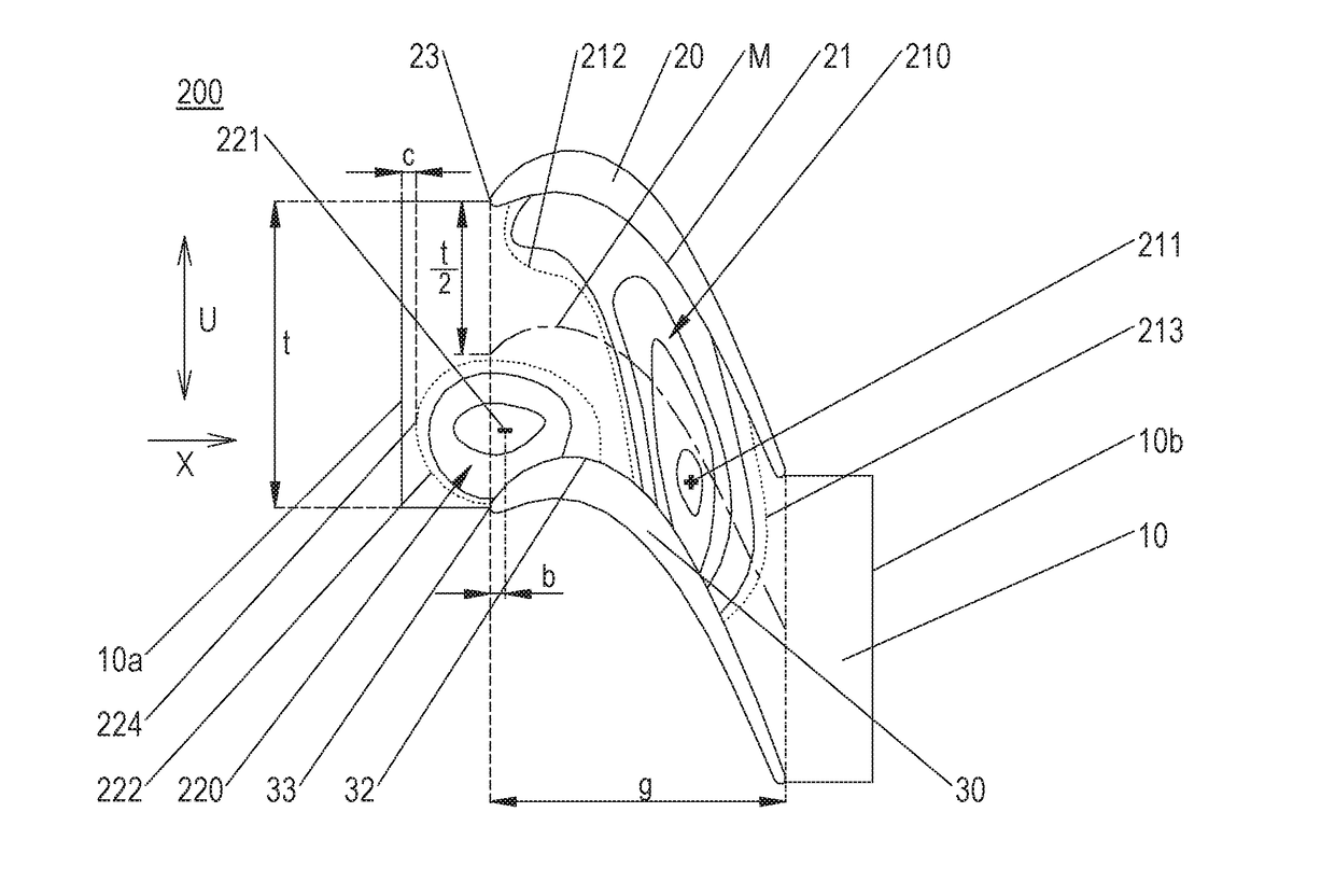
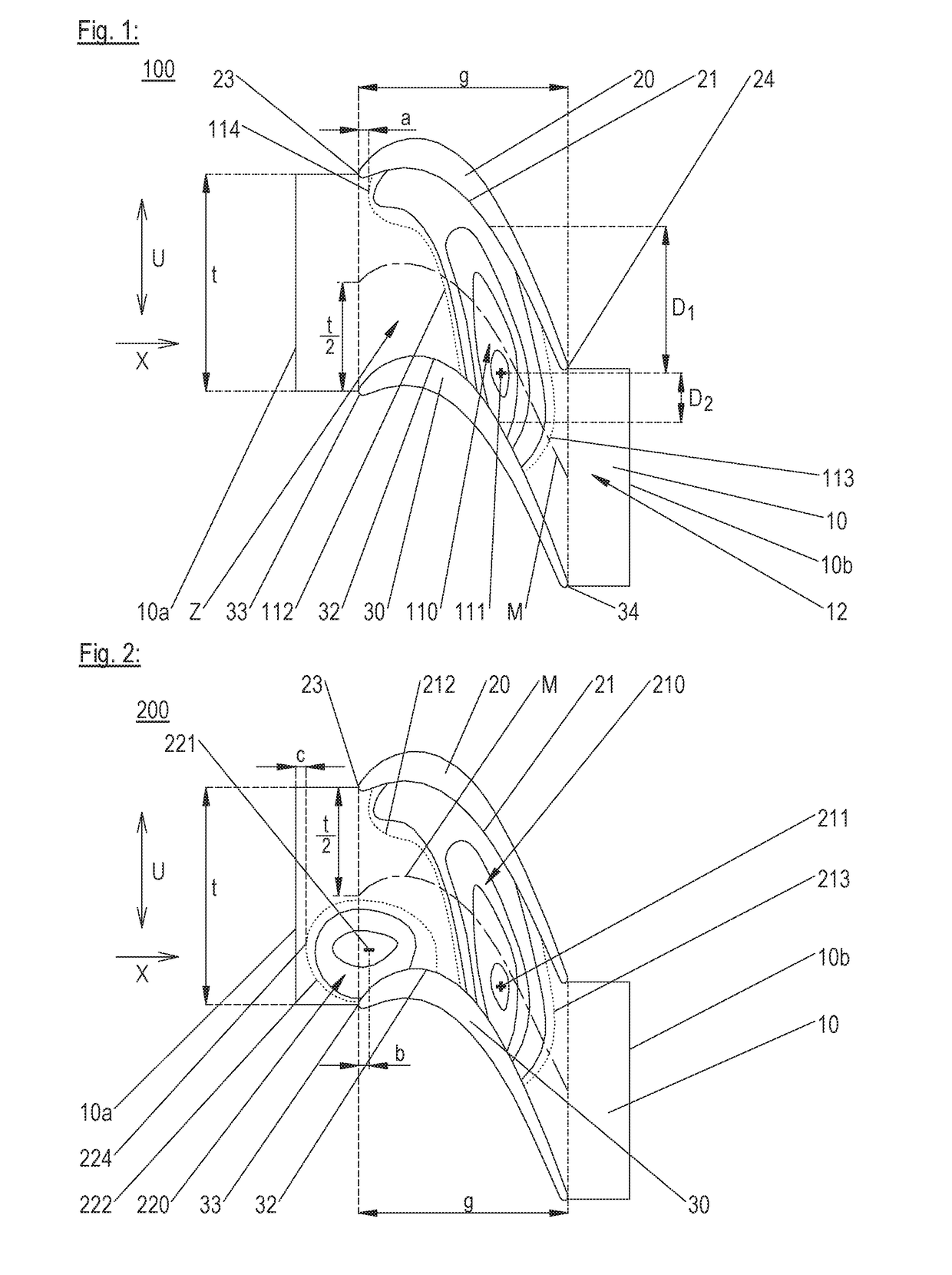
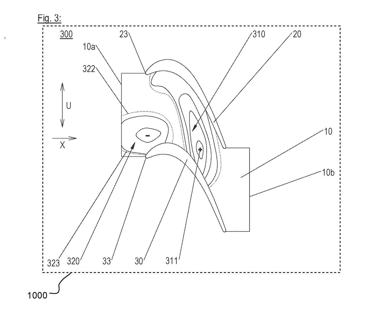
[0048]In a plan view (in a radial direction of view), FIG. 1 schematically shows a developed, exemplary specific embodiment of an airfoil array segment 100 according to the present invention. It includes airfoils 20, 30, which each have a pressure side and a suction side, as well as an inventive platform 10 having a platform surface 12, a leading platform edge 10a and a trailing platform edge 10b (viewed relative to designated primary flow direction X). The platform may have a one-part or two-part form, for example. Specifically, it may include two parts from which one of airfoils 20, 30 projects, respectively.

[0049]The airfoils define an inter-airfoil strip Z as the surface section that is located in circumferential direction U between pressure side 21 of first airfoil 20 and suction side 32 of second airfoil 30 and that, in axial direction X, is bounded at the upstream end by a connection of leading edges 23, 33 of airfoils 20, 30 and at the downstream end by a connection of respe...


PUM


Abstract

Described are an airfoil array segment (100, 200, 300) having at least two airfoils (20, 30) and a platform (10) that features an axis asymmetrical platform surface (12). This platform surface features an elevation (110, 210, 310) that extends from the pressure side (21) of the first to the suction side (32) of the second airfoil (30). A highest point (111, 211, 311) of the elevation is more proximate to the suction side 32 of the second airfoil (30) than to the pressure side (21) of the first airfoil (20). Also described are an airfoil, a platform, an airfoil passage and a turbomachine.

Description

[0001]This claims the benefit of European Patent Application EP17171141.9, filed May 15, 2017 and hereby incorporated by reference herein.[0002]The present invention relates to an airfoil array segment, an airfoil array, a platform, and to an airfoil passage of a turbomachine, as well as to a turbomachine.BACKGROUND[0003]Turbomachines (such as gas and steam turbines) routinely have an airflow passage to allow a fluid to pass therethrough. The airflow passage, also referred to as “annular space,” is radially inwardly bounded by a radially inner endwall, which can be formed, for example, by radially inner rotor blade platforms or by radially inner stator vane platforms, and is configured on the hub side, and, radially outwardly by a radially outer endwall, for example, which can be formed by radially outer rotor blade platforms (also referred to as “shroud”) or by radially outer stator vane platforms, and is configured on the housing side; unless indicated otherwise, the designations ...

Claims


Application Information

Patent Timeline
IPC IPC(8): F01D5/14F01D9/04
CPCF01D5/142F01D9/041F05D2220/32F01D5/143Y02T50/60F01D5/145
Inventor BRETTSCHNEIDER, MARKUSMAHLE, INGAMAATOUK, FADI
Owner MTU AERO ENGINES GMBH
Why Eureka
Try Eureka