Suction nozzle

Active Publication Date: 2018-11-22
DYSON TECH LTD
View PDF0 Cites 5 Cited by
  • Summary
  • Abstract
  • Description
  • Claims
  • Application Information

AI Technical Summary

Benefits of technology

The present invention provides a suction nozzle with three different modes, making it more versatile. When the valve mechanism is placed in the first configuration, the suction nozzle can be tailored for normal use, maximizing suction power but making it easier to move. When the valve mechanism is placed in the second configuration, the suction nozzle can be tailored for picking up large debris, sacrificing maneuverability but maximizing suction through the auxiliary suction path and the main suction opening. When the valve mechanism is placed in the third configuration, the suction nozzle can be tailored for maximum suction power at the main suction opening but sacrificing maneuverability, closing both the auxiliary suction path and the bleed path. This allows for a vacuum cleaner with a suction nozzle that provides improved versatility.

Problems solved by technology

However, the low pressure inside the suction nozzle with the large debris path closed can cause the suction nozzle to ‘limpet’—sucking itself down onto a floor surface and therefore being difficult to manoeuvre.
However, the provision of an additional route for air into the suction nozzle would further reduce suction at the main suction opening and thus potentially reduce overall performance.

Method used


Image

  • Suction nozzle
  • Suction nozzle
  • Suction nozzle

Examples


Embodiment Construction

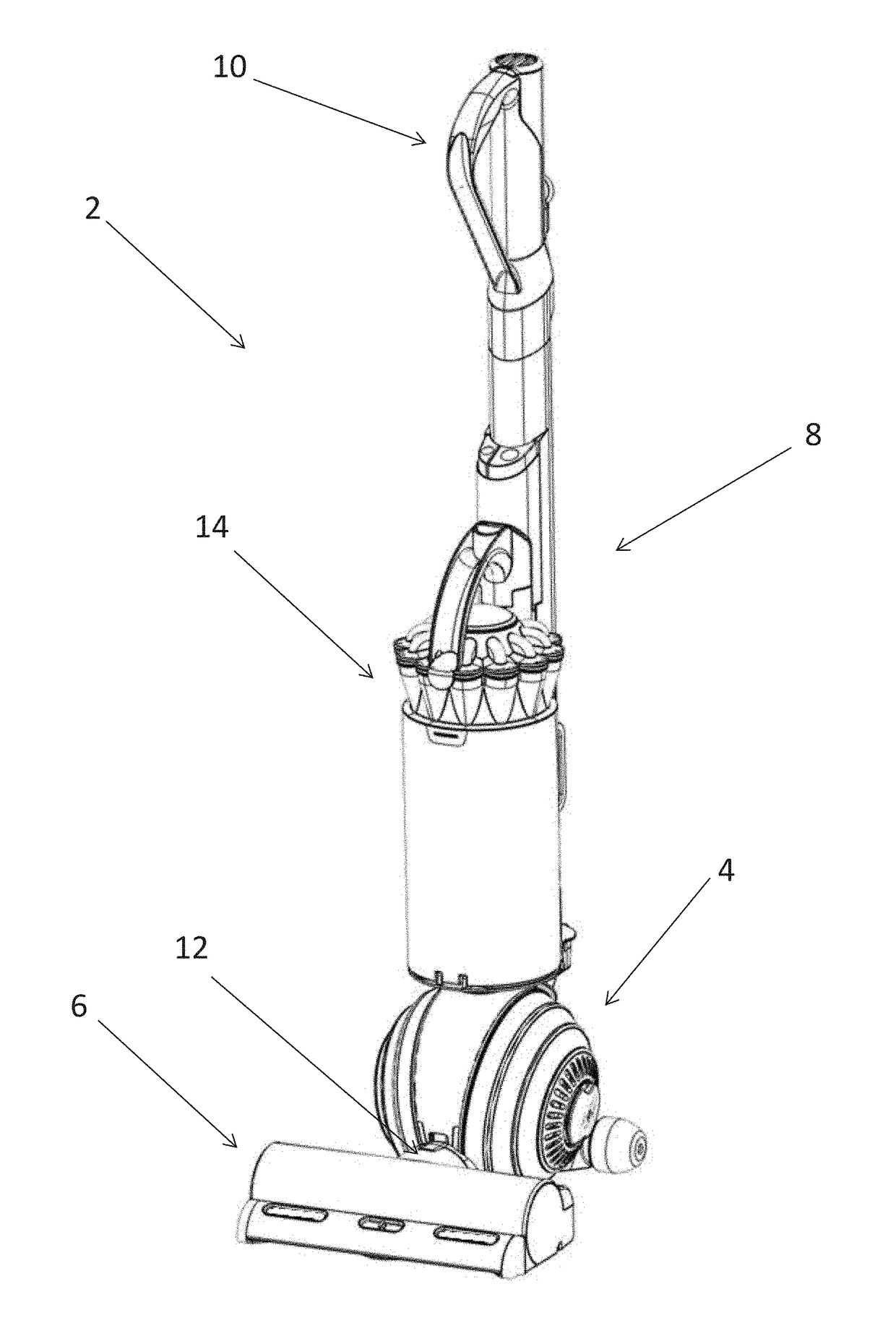
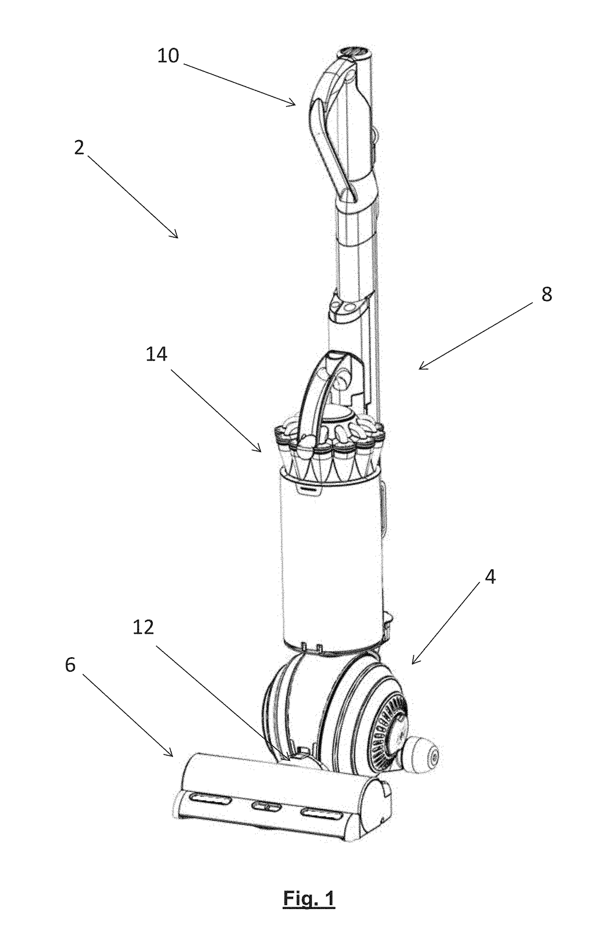
[0068]FIG. 1 shows a vacuum cleaner 2 according to an embodiment of the invention. The vacuum cleaner 2 of this embodiment is an upright vacuum cleaner. It has a rolling assembly 4 which carries a suction nozzle 6, and an ‘upright’ body 8. The upright body 8 can be reclined relative to the head assembly 4, and includes a handle 10 for maneuvering the vacuum cleaner 2 across the floor. In use, a user grasps the handle 10 and reclines the upright body 8 until the handle 10 is disposed at a convenient height. The user can then roll the vacuum cleaner 2 across the floor using the handle 10 in order to pass the suction nozzle 6 over the floor and pick up dust and debris therefrom. The dust and debris is drawn into the suction nozzle by a suction generator in the form of a motor-driven fan (not visible) housed on board the vacuum cleaner 2, and is ducted in conventional manner under the fan-generated suction pressure from an outlet duct 12 of the suction nozzle to a cyclonic separating ap...


PUM


Abstract

A suction nozzle for a vacuum cleaner includes a suction chamber; an outlet duct; an underside for engaging a surface to be cleaned; a main suction opening in the underside, which opens into the suction chamber; an auxiliary suction path which opens into the suction chamber; and a bleed path in fluid communication with the outlet duct. The suction nozzle further includes a valve mechanism arranged to open and close the auxiliary suction path and the bleed path, the valve mechanism being movable between a first configuration in which the auxiliary suction path is closed and the bleed path is open, a second configuration in which the auxiliary suction path is open and the bleed path is closed, and a third configuration in which both the auxiliary suction path and the bleed path are closed.

Description

REFERENCE TO RELATED APPLICATIONS[0001]This application claims the priority of United Kingdom Application No. 1707991.4, filed May 18, 2017, the entire contents of which are incorporated herein by reference.FIELD OF THE INVENTION[0002]The present invention relates to a suction nozzle of the type that can be used on a vacuum cleaner.[0003]The invention is not limited to suction nozzles for any particular type of vacuum cleaner. For example, it includes both cleaner heads on upright vacuum cleaners and floor tools on cylinder vacuum cleaners or handheld vacuum cleaners.BACKGROUND OF THE INVENTION[0004]One way of characterizing the cleaning performance of a vacuum cleaner is by reference to its so-called ‘pick-up’ performance: the ability of the vacuum cleaner to pick up dirt and debris from a floor surface. A desirable pick-up performance often includes the ability to pick up both fine dirt as well as so-called ‘large debris’ such as, for example, certain pet snacks, breakfast cereals...

Claims


Application Information

Patent Timeline
IPC IPC(8): A47L9/00A47L9/02A47L5/22
CPCA47L9/0072A47L9/02A47L5/225A47L9/244A47L9/04
Inventor MCINTOSH, DONALD JAMESCARSWELL, JAMES ROBERTSTEPHENS, LUKE WILLIAM
Owner DYSON TECH LTD
Why Eureka
Try Eureka