Filter Element and Fluid Filter

a filter element and fluid filter technology, applied in the direction of filtration separation, membrane technology, separation processes, etc., can solve the problem of difficult to move the filter element out of the filter housing in order to replace the filter element, and achieve the effect of preventing the mixing of clean fluid

Active Publication Date: 2018-11-22
MANN HUMMEL GMBH
View PDF1 Cites 1 Cited by
  • Summary
  • Abstract
  • Description
  • Claims
  • Application Information

AI Technical Summary

Benefits of technology

[0013]The filter element according to the invention is characterized by simpler handing overall, in that one of the two sealing elements of the seal comprises a sealing lip that extends away from the sealing connecting piece in the radial direction, and the other of the two sealing elements, respectively, is formed as an oil seal. An oil seal is understood to be an annular sealing element without a sealing lip. The oil seal may equally comprise a sealing edge. The oil seal can ensure simplified guidance of the filter element on the filter housing when the filter element is inserted into the operating position thereof inside a filter housing of an oil filter or fuel filter. It is thus easy to orient the sealing connecting piece so as to be axially aligned with the drainage channel and to thread the sealing connecting piece therein. In this case, when the sealing connecting piece is introduced into the drainage channel of the filter housing, the elastically deformable sealing lip of the other sealing element, respectively, is deflected out of the neutral position thereof, i.e. the unstressed position thereof, in the radial direction relative to the sealing connecting piece, counter to the inherent elasticity of the material of the sealing lip, so as to come into contact with a side wall of the drainage channel. Manufacturing tolerances of the filter element and of a filter housing of a fuel filter or oil filter that is intended for receiving the filter element can be compensated for in this design of the seal.
[0014]Moreover, the sealing lip is designed so as to be pressed against the associated side wall by means of a contact pressure derived from the pressurization by means of the fluid, i.e. in a pressure-assisted manner. A further improved sealing function of the seal can be achieved thereby. In this case, the sealing lip of a sealing element extends away from the sealing connecting piece preferably in the axial direction toward the filter medium. As a result, the sealing lip can be applied to the associated side wall of the drainage channel in a pressure-assisted or pressure-proportional manner in the case of pressurization by the pressurized fluid. The sealing lip is thus applied to the side wall of the drainage channel at a contact pressure that is pressure-proportional to the operating pressure of the fluid. As a result, reliable sealing of the drainage channel with respect to the pressurized fluid is achieved irrespective of an operating pressure prevailing in the fluid.
[0016]According to the invention, the radially inner sealing element preferably comprises the sealing lip. This results in particularly simple mounting of the filter element in the filter housing of a fluid filter. The effects of a swelling-related increase in volume of the radially outer oil seal are reduced compared with an inner oil seal. Removal of the filter element from the sealing seat thereof inside a filter housing of a fluid filter is thus impeded to a lesser extent. In the case of the radially outer oil seal, it is possible to compensate for manufacturing tolerances of the sealing connecting piece or of the fluid channel on the filter housing side more reliably than is the case for an oil seal that is arranged on the inside of the sealing connecting piece in the radial direction.
[0017]According to the invention, the cross section of the sealing lip of one of the sealing elements may taper toward the free end thereof. This can improve the response characteristic of the sealing lip to operating pressure fluctuations of the fluid flowing through the filter element.
[0021]With regard to aspects of manufacturing, it has been found to be advantageous for the sealing connecting piece to be formed by an end plate of the filter element. As a result, separate components are no longer required, and mounting of the filter element is facilitated as a whole.
[0025]The seal or the side walls of the drainage channel may be designed such that respective fluidic connections of the drainage channel to the untreated fluid side and to the clean fluid side are released in succession when the filter element is removed. It is thus possible to largely prevent the clean fluid from mixing with the unfiltered fluid.

Problems solved by technology

Moreover, the double concentric seal may swell due to long-term contact with the oil, with the result that it is often difficult to move the filter element out of the filter housing in order to replace the filter element.

Method used


Image

  • Filter Element and Fluid Filter
  • Filter Element and Fluid Filter
  • Filter Element and Fluid Filter

Examples


Embodiment Construction

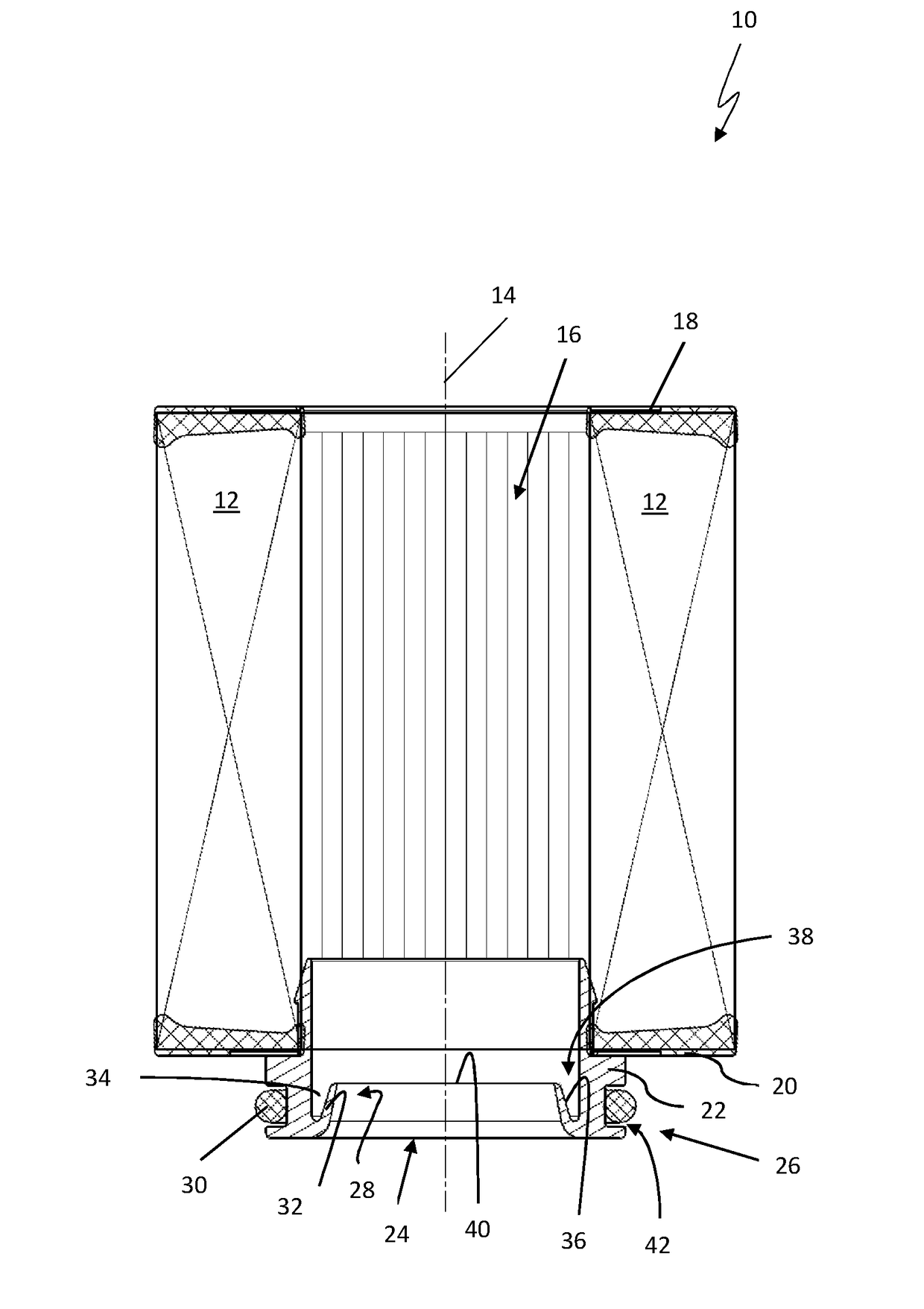
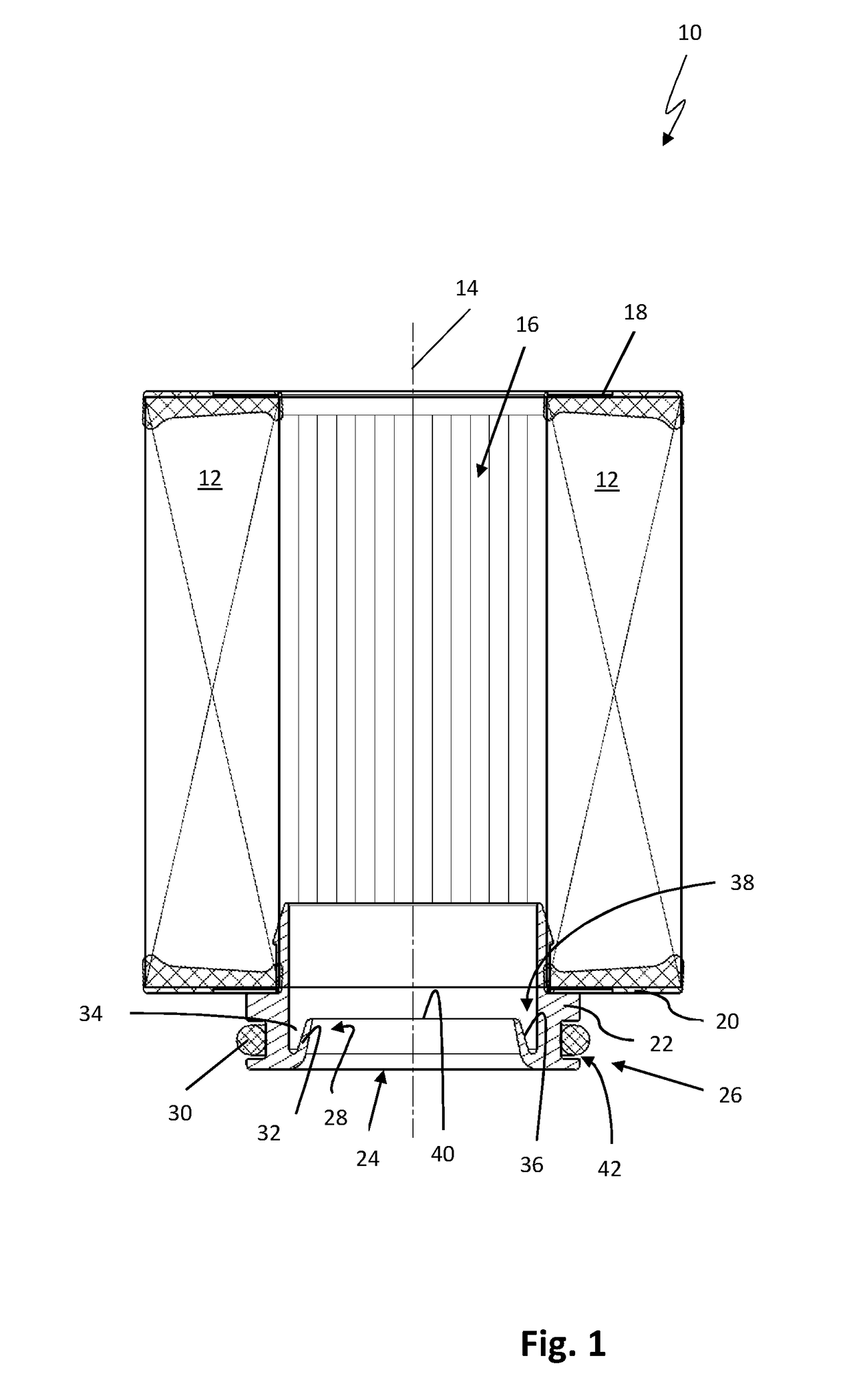
[0029]FIG. 1 shows a filter element 10 for filtering out contaminants contained in a fluid such as oil or fuel. The filter element 10 comprises a filter medium 12 that is arranged in an annular manner with respect to the longitudinal axis 14 of the filter element 10 and completely surrounds an axially extending inner cavity 16 of the filter element 10. As shown in FIG. 1, the filter medium 12 can be designed as a stellate folded bellows and consist of a nonwoven fabric for example. The filter medium 12 is arranged so as to be retained between an upper and a lower end plate 18, 20 of the filter element 10. For reasons of tightness, the filter medium 12 may in particular be embedded in the material of the end plates or adhesively bonded to the two end plates 18, 20. The fluid to be filtered can pass through the filter medium 12 in a radial direction, from the outside to the inside.

[0030]The filter element 10 comprises a sealing connecting piece 22 at one end. The sealing connecting pi...


PUM

PropertyMeasurementUnit
forceaaaaaaaaaa
elasticityaaaaaaaaaa
contact pressureaaaaaaaaaa

Abstract

A filter element for filtering fluid has a filter medium surrounding an inner cavity extending axially in the filter element. An axially extending sealing connecting piece is arranged at an axial end of the filter element. The sealing connecting piece has an opening fluidically connecting the inner cavity to a fluid channel of a filter housing and also has a seal holder structure. A double concentric seal is arranged at the sealing connecting piece and closes a drainage channel of the filter housing. The double concentric seal has radially inner and radially outer sealing elements. One of the sealing elements has an elastically deformable sealing lip that extends away from the sealing connecting piece radially and axially toward the filter medium and can be pressed against a sidewall of the drainage channel of the filter housing. The other sealing element is an oil seal arranged in the seal holder structure.

Description

CROSS-REFERENCE TO RELATED APPLICATIONS[0001]This application is a continuation application of international application No. PCT / EP2017 / 050636 having an international filing date of 13 Jan. 2017 and designating the United States, the international application claiming a priority date of 1 Feb. 2016, based on prior filed German patent application No. 10 2016 001 023.1, the entire contents of the aforesaid international application and the aforesaid German patent application being incorporated herein by reference.BACKGROUND OF THE INVENTION[0002]The invention relates to a filter element and to a fluid filter for filtering a fluid, in particular fuel or oil, comprising a filter medium which surrounds an inner cavity extending along a filter element longitudinal axis, and one end of which comprises a sealing connecting piece comprising an opening for fluidically connecting the inner cavity to a fluid channel of a filter housing. The sealing connecting piece comprises a seal having a rad...

Claims


Application Information

Patent Timeline
Patent Type & Authority Applications(United States)
IPC IPC(8): B01D29/13B01D35/30
CPCB01D29/13B01D35/30B01D2201/347B01D2201/4084
Inventor VOGT, CHRISTIAN
Owner MANN HUMMEL GMBH
Why Eureka
Try Eureka