
Vehicle lighting system with directional control

a technology of vehicle lighting and directional control, applied in the field of vehicle lighting, can solve problems such as distracting interaction with such sensors

Inactive Publication Date: 2018-11-29
FORD GLOBAL TECH LLC
View PDF14 Cites 5 Cited by
  • Summary
  • Abstract
  • Description
  • Claims
  • Application Information

AI Technical Summary

Benefits of technology

The present disclosure is about a vehicle lighting apparatus that has the ability to move in multiple directions and directs a light source to a specific location in the vehicle. This allows for precise control over the location and direction of the emitted light, resulting in improved visibility and safety for drivers and passengers.

Problems solved by technology

Accordingly, interaction with such sensors can be distracting.

Method used


Image

  • Vehicle lighting system with directional control
  • Vehicle lighting system with directional control
  • Vehicle lighting system with directional control

Examples


Embodiment Construction

[0014]As required, detailed embodiments of the present disclosure are disclosed herein.

[0015]However, it is to be understood that the disclosed embodiments are merely exemplary of the disclosure that may be embodied in various and alternative forms. The figures are not necessarily to a detailed design and some schematics may be exaggerated or minimized to show function overview. Therefore, specific structural and functional details disclosed herein are not to be interpreted as limiting, but merely as a representative basis for teaching one skilled in the art to variously employ the present disclosure.

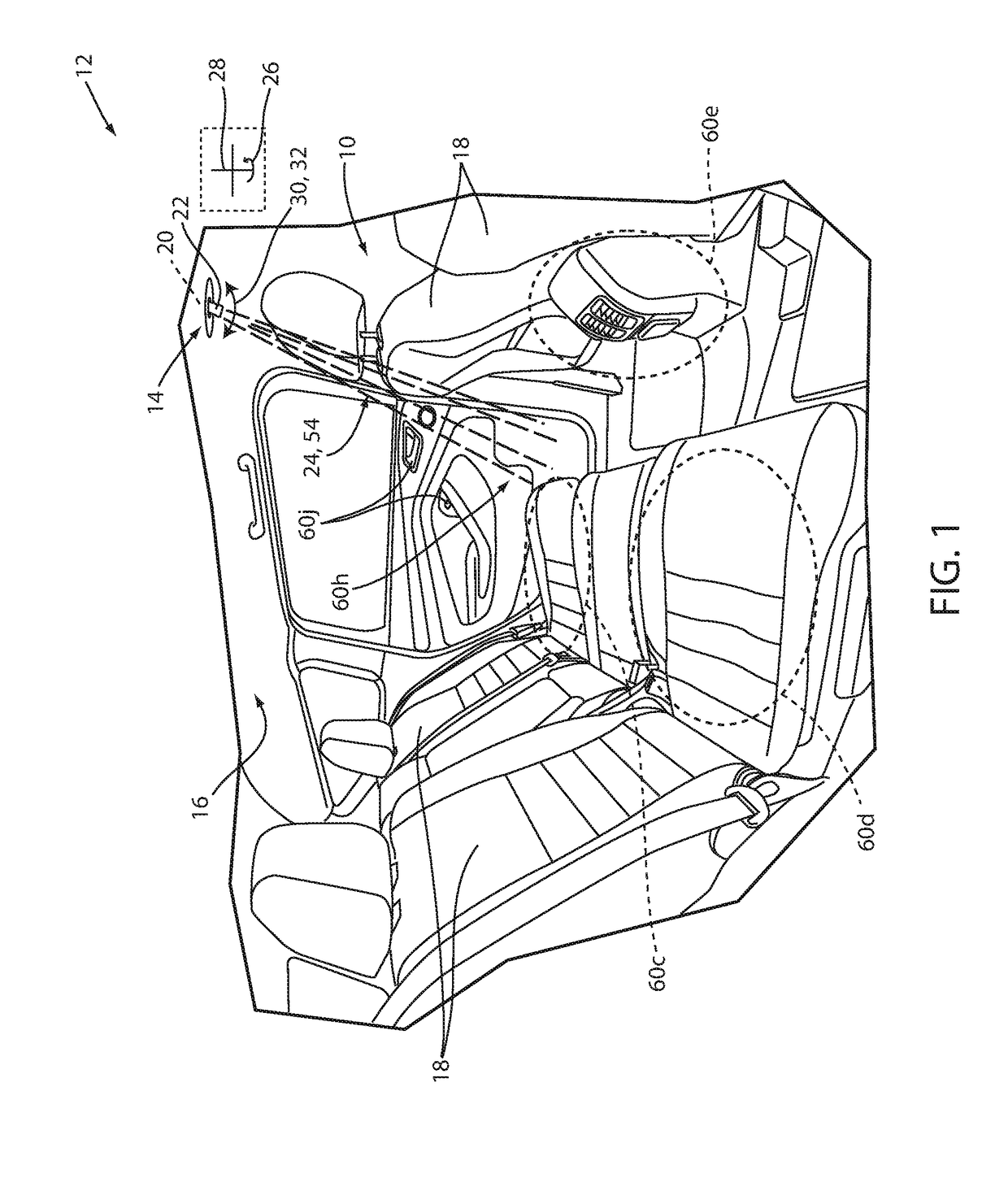
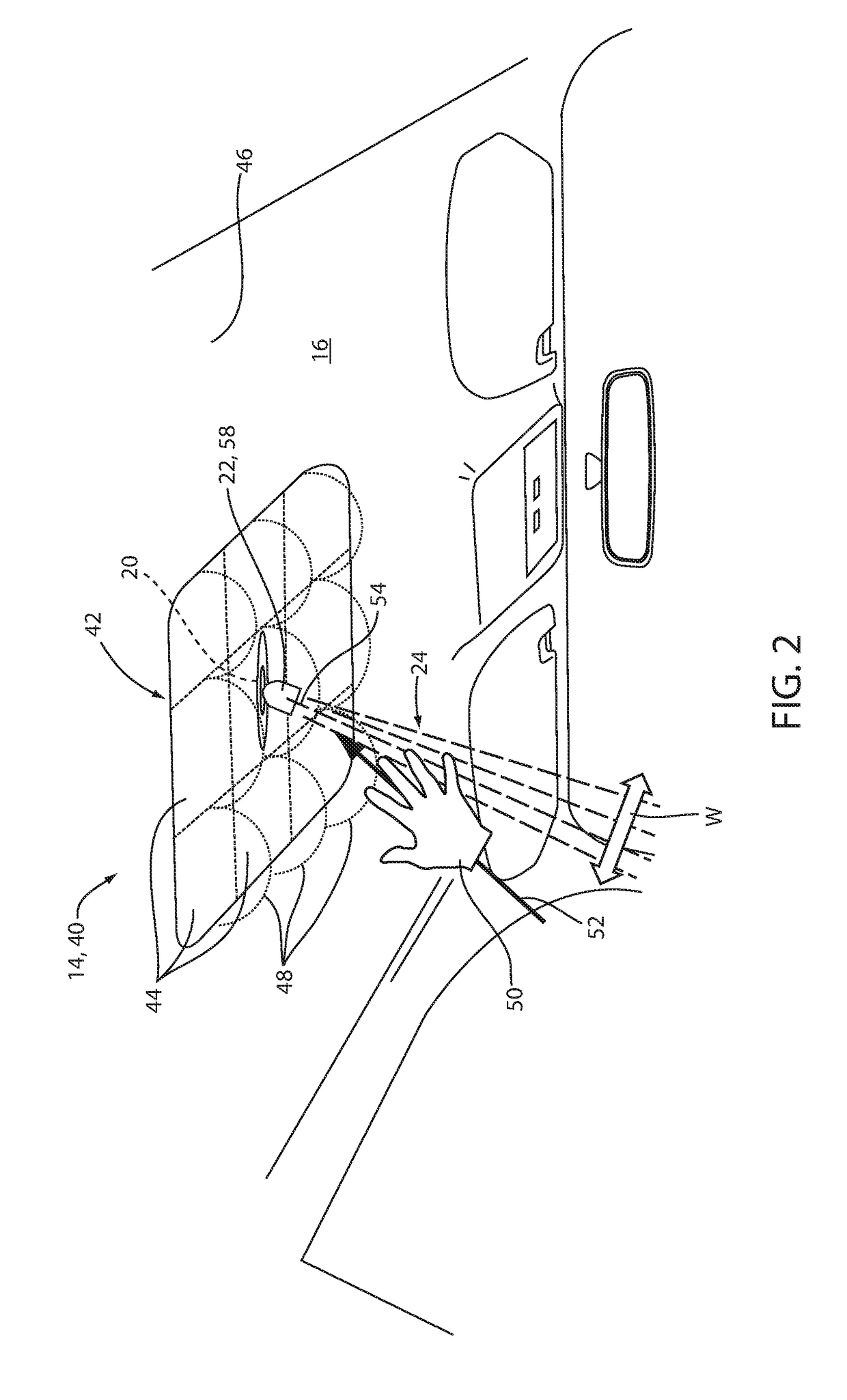
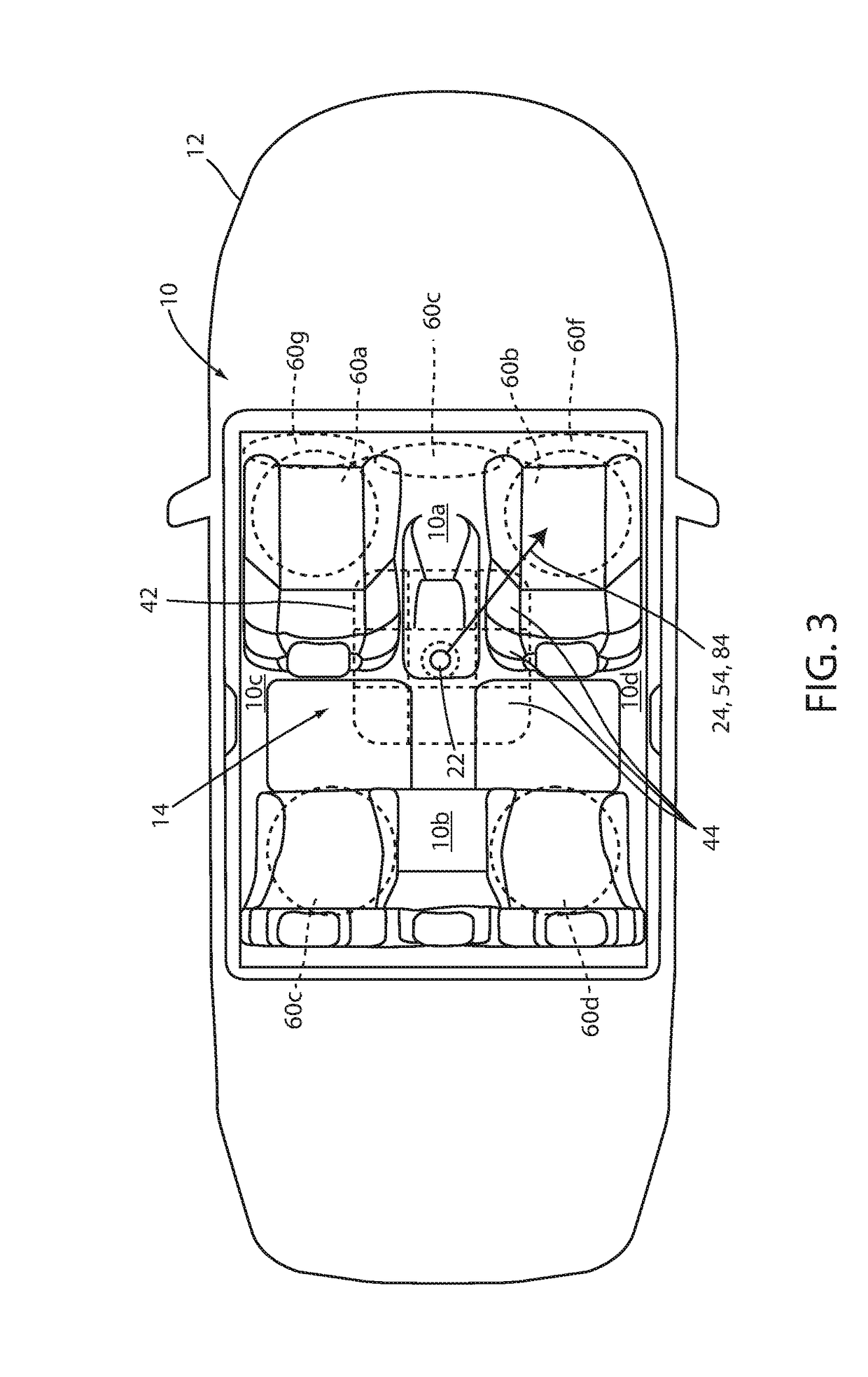
[0016]Referring to FIG. 1, a vehicle passenger compartment 10 or cabin of an automotive vehicle 12 is generally illustrated comprising a lighting apparatus 14. The lighting apparatus 14 may be disposed in an overhead console or headliner 16 of the vehicle 12. In the illustrated embodiment, the lighting apparatus 14 may be located centrally in the headliner 16 relative to a plurality of ...


PUM


Abstract

A vehicle lighting apparatus is disclosed. The apparatus comprises a positioning apparatus configured to provide multi axis motion and a light source configured to output an emission in connection with the apparatus. The apparatus further comprises a light controller in communication with the positioning apparatus and the light source. The light controller is configured to control the positioning apparatus to orient the light source directing the emission to a location in the vehicle.

Description

FIELD OF THE DISCLOSURE[0001]The present disclosure generally relates to vehicle lighting, and more particularly to directional interior vehicle lighting.BACKGROUND OF THE DISCLOSURE[0002]Some lighting devices require a user interaction that is not intuitive. Accordingly, interaction with such sensors can be distracting. The disclosure provides for a lighting system to improve on various systems presently available.SUMMARY OF THE DISCLOSURE[0003]According to one aspect of the present disclosure, a vehicle lighting apparatus is disclosed. The apparatus comprises a positioning apparatus configured to provide multi axis motion and a light source configured to output an emission in connection with the apparatus. The apparatus further comprises a light controller in communication with the positioning apparatus and the light source. The light controller is configured to control the positioning apparatus to orient the light source directing the emission to a location in the vehicle.[0004]A...

Claims


Application Information

Patent Timeline
Patent Type & Authority Applications(United States)
IPC IPC(8): B60Q3/80B60Q3/54F21V14/02F21V23/04B60Q3/76
CPCB60Q3/80B60Q3/54F21V14/02B60Q3/225B60Q3/76B60Q2500/10B60Q2400/40F21V23/0471B60Q3/51B60Q3/85B60Q1/323B60Q3/74F21W2106/00F21S43/16B60Q1/247
Inventor SALTER, STUART C.DELLOCK, PAUL KENNETHBUTTOLO, PIETROSINGER, JEFFREYSURMAN, JAMES J.
Owner FORD GLOBAL TECH LLC
Learn More