
Lever-type connector

a connector and lever-type technology, applied in the direction of connection, electrical apparatus, coupling device connection, etc., can solve the problems of disadvantageous heavy workload, hole complicating structure, and needing to remove male terminal fittings, etc., and achieve the effect of not being particularly difficult to cancel operation

Active Publication Date: 2018-12-06
SUMITOMO WIRING SYST LTD
View PDF17 Cites 1 Cited by
  • Summary
  • Abstract
  • Description
  • Claims
  • Application Information

AI Technical Summary

Benefits of technology

The patent describes a device for safely and efficiently removing male terminal fittings from electronic equipment without the need for a jig. The device includes a lever with a stopper and a cam plate that can be deformed elastically to cancel their locking. A guide groove is formed to easily displace the cam plate using a tool. The front retainer does not need a jig insertion hole because it is detached from the hood when the lever is attached to the housing. An arc-like groove and interference portion control the further swinging of the lever. The technical effects of the device include improved safety, efficiency, and ease of use.

Problems solved by technology

However, the male terminal fitting may have to be removed from the housing for maintenance.
More specifically, before the detaching operation of the moving plate, the removing operation of the lever must be performed, and therefore the workload is disadvantageously heavy.
However, the jig insertion hole complicates the structure, and resin fluidity is deteriorated.
Accordingly, a shaping property of the moving plate may be deteriorated.
Thus, a jig insertion hole must be formed in the front retainer, and the structure becomes further complex.
The formation of a jig insertion hole in the front retainer for receiving a terminal removing jig could deteriorate the resin fluidity of the front retainer.

Method used


Image

  • Lever-type connector
  • Lever-type connector
  • Lever-type connector

Examples


Embodiment Construction

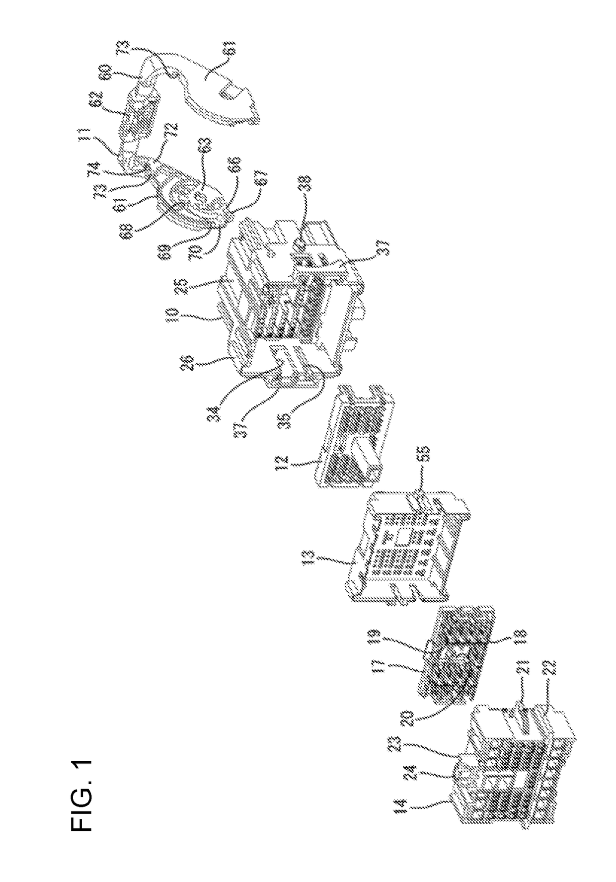
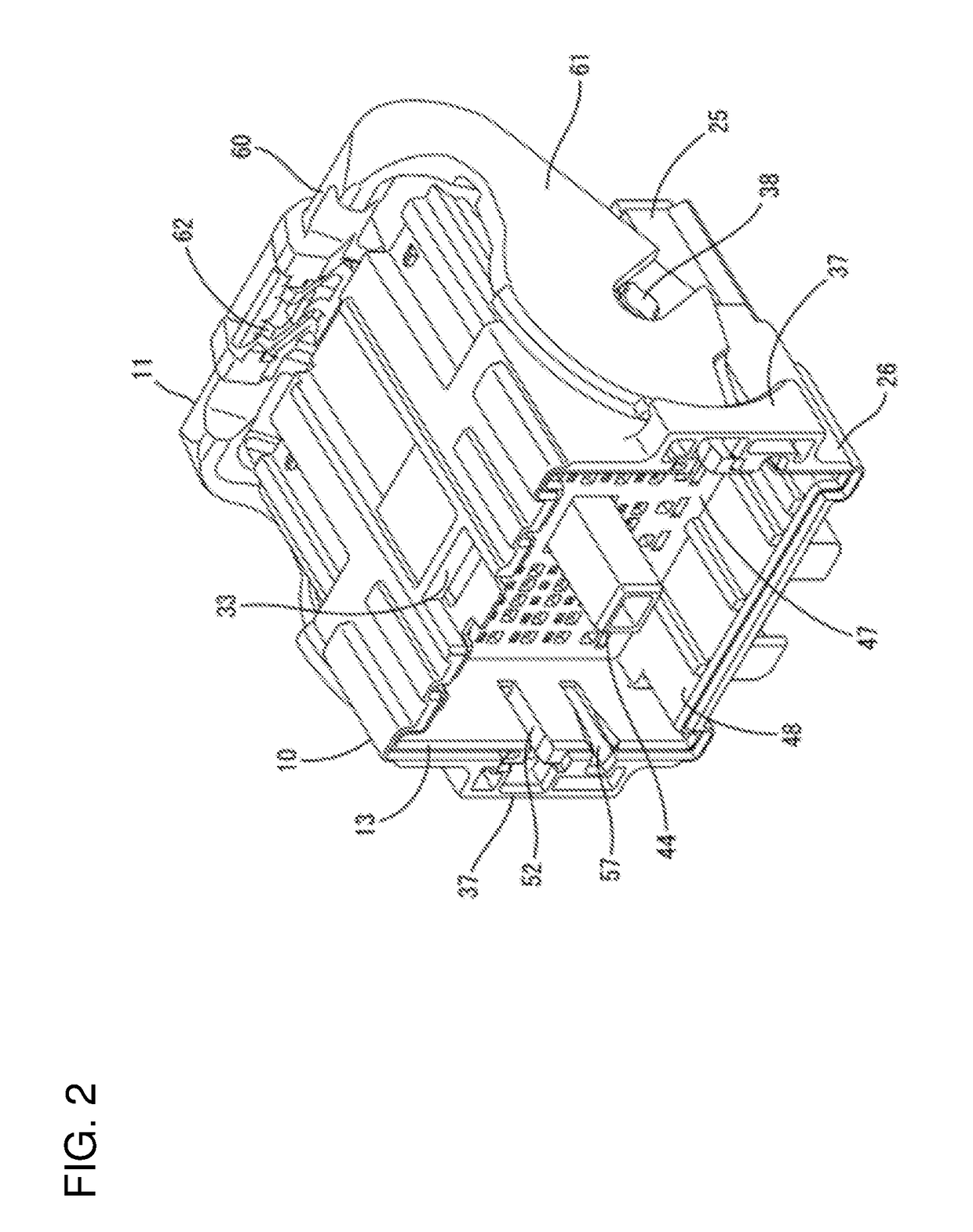
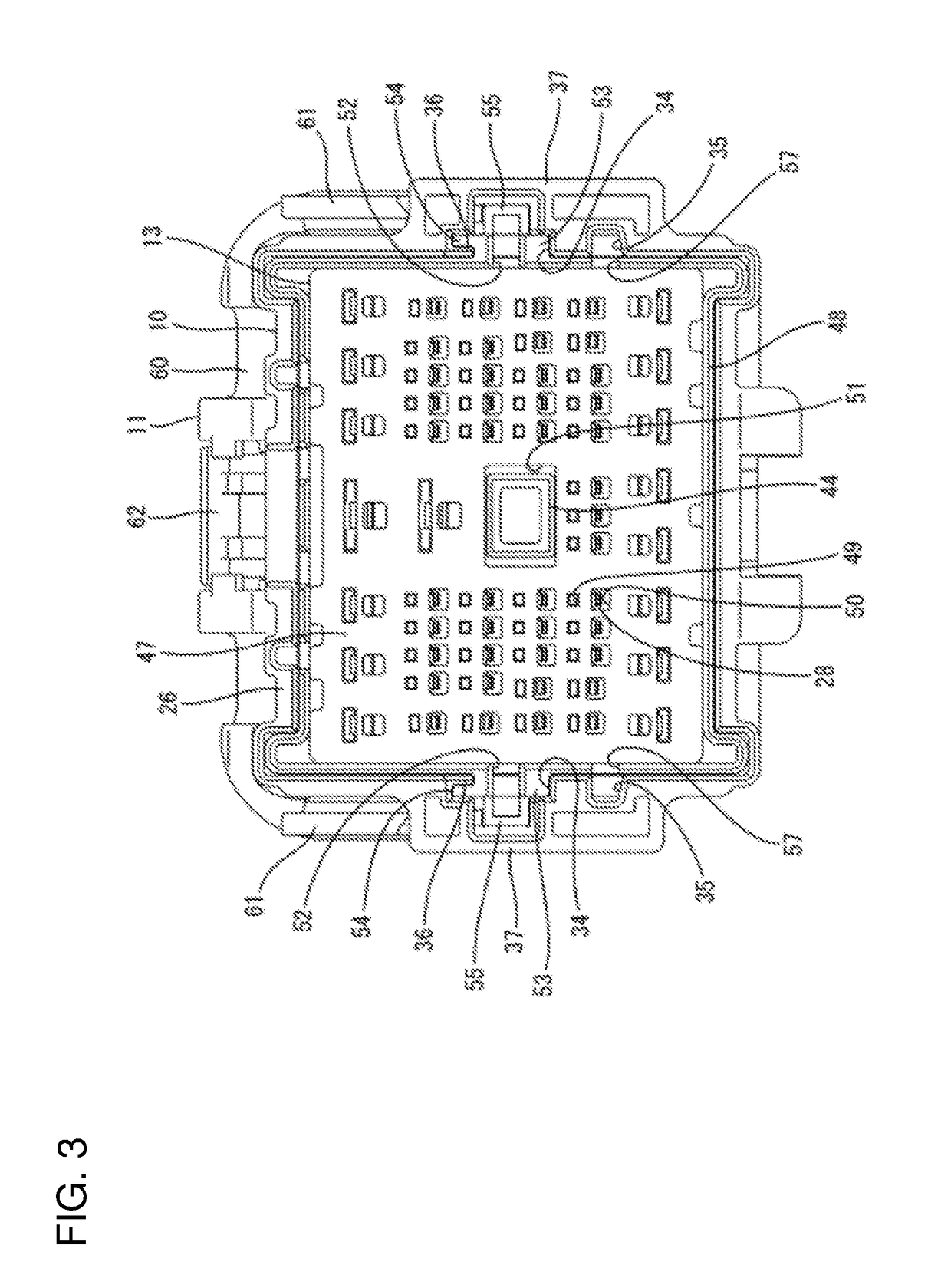
[0036]An embodiment of the invention will be described below with reference to FIGS. 1 to 17. A lever-type connector according to this embodiment, as shown in FIG. 1, includes a housing 10, a front retainer 12, and at least one moving plate 13. The housing 10 can be fit on a counterpart mating housing 14. In the following description, it is assumed that, with respect to forward and backward directions, substantially facing ends on which both housings 10 and 14 face each other at a start of fitting are defined as front ends. Vertical directions and horizontal directions mean up and down directions and width directions, respectively, and are defined on the basis of FIG. 3 and FIG. 17.

[0037]The counterpart housing 14 is made e.g. of a synthetic resin and, as shown in FIG. 17, has a substantially rectangular-block-like shape. Counterpart cavities 15 are disposed to align in the vertical and horizontal directions in the counterpart housing 14. Each of the counterpart cavities 15 can rece...


PUM


Abstract

A lever (11) swings from a fitting start position to a fitting completion position on a housing (10) and has a cam groove (68). In the swinging process, a cam follower (21) of a counterpart housing (14) and cam (55) of a moving plate (13) advance a fitting operation between the housings (10) and (14) to move the moving plate (13) from a moving start position to a moving completion position. A detachment regulating portion (69) locks the cam (55) at the fitting start position to regulate detachment of the moving plate (13) from the hood (26). The lever (11) is swung from the fitting start position in an opposite direction of the fitting completion position, and has a detachment allowing position separating the cam (55) from the detachment regulating portion (69) to allow the moving plate (13) to detach from the hood (26).

Description

BACKGROUNDField of the Invention[0001]The invention relates a lever-type connector.Description of the Related Art[0002]Japanese Patent Publication No. 3244034 discloses a lever-type connector that includes a male housing having a hood in which a counterpart female housing can be fit. The male housing has a male terminal fitting with a tab projecting into the hood. A lever is supported swingably at a fitting start position and a fitting completion position with respect to the male housing. Additionally, a moving plate is arranged movably at a tab holding position (moving start position) and a holding canceling position (moving completion position) in the hood. The moving plate has a positioning hole at which the tab of the male terminal fitting is positioned and into which the tab can be inserted so that the distal end of the tab projects through the positioning hole at the tab holding position in a protected state.[0003]Cam pins (cam follower and cam) are disposed on the female hous...

Claims


Application Information

Patent Timeline
Patent Type & Authority Applications(United States)
IPC IPC(8): H01R13/629H01R13/422
CPCH01R13/62977H01R13/4223H01R13/502H01R13/6275H01R13/629H01R13/7035H01R13/4365H01R13/4538H01R13/62938
Inventor MAMIYA, YUMAIMAI, YUJIRO
Owner SUMITOMO WIRING SYST LTD
Learn More