Plantar Arch Support Shoe

a plantar arch and shoe technology, applied in the field of shoes, can solve the problems of providing support for the plantar arch cannot be moved upwards or secured, and achieve the effect of convenient attachment, convenient pulling toward the upper part of the shoe, and convenient pulling upwards of the plantar arch of the foot of the user

Inactive Publication Date: 2018-12-13
TOPGOLF CALLAWAY BRANDS CORP
View PDF7 Cites 5 Cited by
  • Summary
  • Abstract
  • Description
  • Claims
  • Application Information

AI Technical Summary

Benefits of technology

[0007]According to the present invention, the wire is wound by the dial unit, so that the leading end section of the belt can be pulled toward the outer side surface of the upper, and the belt can be fastened to the foot of the user wearing the shoe. In this structure, the base end section of the belt is fixed to the outsole at the position equivalent to the plantar arch, and both side edges of the belt in the longitudinal direction of the shoe are not fixed to the upper, so when the belt is fastened, the base end section of the belt and the fixing portion of the outsole can be efficiently pulled toward an upper part of the shoe. Consequently, it is possible to easily push the plantar arch of the foot of the user upward. When the belt is thereby fastened to the foot of the user, the plantar arch is supported.
[0008]A pair of openings for drawing out the wire can be provided in the dial unit. The pair of openings face the guide member in the direction of fasten...

Problems solved by technology

The prior art structure disclosed in Japanese Patent Laid-Open No. 2015-519949 does not, however, provide support for the plantar arch of the foot.
This prior art s...

Method used


Image

  • Plantar Arch Support Shoe
  • Plantar Arch Support Shoe
  • Plantar Arch Support Shoe

Examples


Embodiment Construction

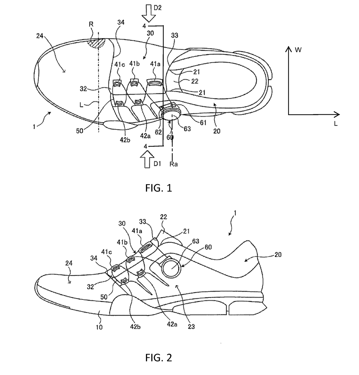
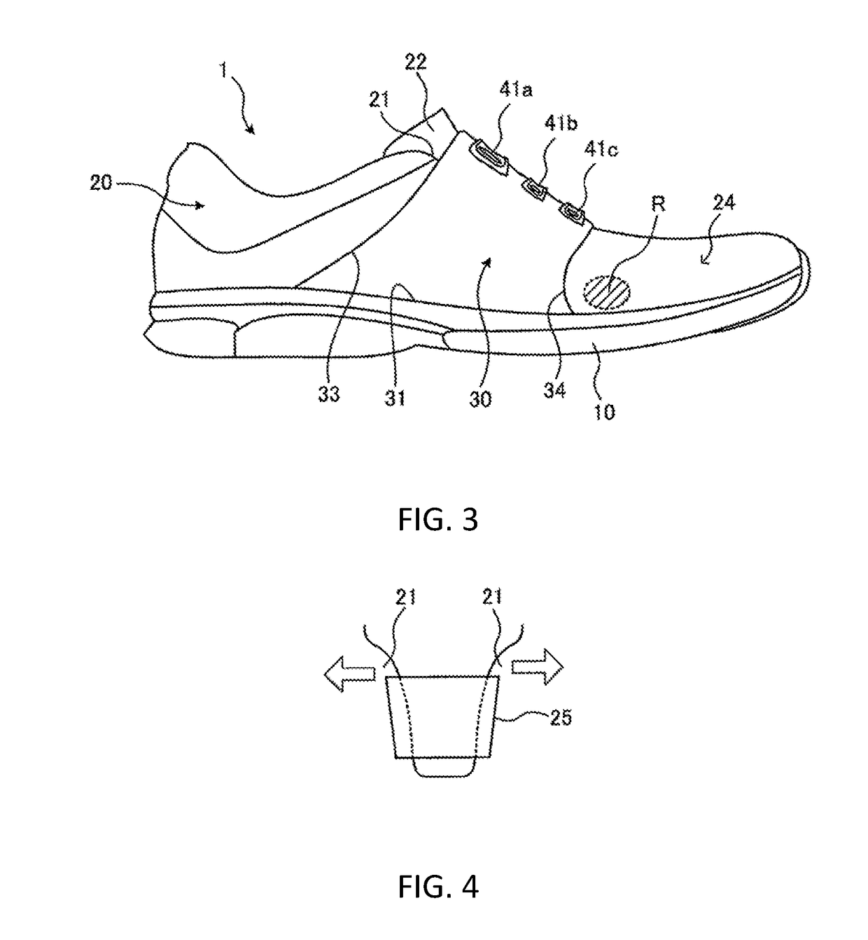
[0019]A shoe according to a first, preferred embodiment of the present invention is shown in FIGS. 1-3. FIG. 1 is a plan view of the shoe of this embodiment, FIG. 2 is a side view of the shoe as viewed from the direction of an arrow D1 illustrated in FIG. 1, and FIG. 3 is a side view of the shoe as viewed from the direction of an arrow D2 illustrated in FIG. 1. The shoe 1 has an outsole 10, an upper 20, and a belt 30. An insole (not illustrated) is disposed on a bottom surface of the inside of the shoe 1. The shape of a bottom surface of the outsole 10, which contacts the ground, can be determined by a person skilled in the art. For example, the bottom surface of the outsole 10 may be irregular.

[0020]The belt 30 fastens a foot, and particularly the instep, of a wearer of the shoe 1. The belt 30 covers an area (an inner side surface and an upper surface) of a part of the upper 20. In particular, the belt 30 covers an area equivalent to an area from the plantar arch to the instep of t...


PUM


Abstract

A shoe providing support for the plantar arch of a foot is disclosed herein. The shoe includes a belt, guide members, and a dial unit. The belt includes a base end section fixed to an outsole at a position equivalent to a plantar arch of a foot of a user, and a leading end section covering a pair of blades. Both side edges of the belt can be separated from an upper of the shoe along a longitudinal direction of the shoe. The guide members are fixed to the leading end section of the belt, and engage with a wire, which engages the dial unit. The dial unit is used to wind the wire, thereby tightening or loosening the belt, and therefore the shoe to a wearer's foot, and is fixed to an outer side surface of the upper.

Description

CROSS REFERENCES TO RELATED APPLICATIONS[0001]The present application claims priority to Japanese Patent Applicant Number 2017-115852, filed on Jun. 13, 2017, the disclosure of which is hereby incorporated by reference in its entirety herein.STATEMENT REGARDING FEDERALLY SPONSORED RESEARCH OR DEVELOPMENT[0002]Not ApplicableBACKGROUND OF THE INVENTIONField of the Invention[0003]The present invention relates to a shoe with a wire fastening structure for attaching an upper portion of the shoe to a wearer's foot.Description of the Related Art[0004]In the tongueless footwear described in Japanese Patent Laid-Open No. 2015-519949, shoe lateral sections and a canopy are provided with respective anchor sections, and a cord section is engaged with these anchor sections. Additionally, the cord section is connected to a cord tensioner, and the cord section is tensed by the cord tensioner to fasten the canopy to a foot of a user.[0005]The prior art structure disclosed in Japanese Patent Laid-Op...

Claims


Application Information

Patent Timeline
IPC IPC(8): A43B7/14A43B7/28A43B5/00
CPCA43B7/1475A43B7/1445A43B7/28A43B5/001A43B23/26A43C11/165A43B7/1495A43B7/18
Inventor ONODA, TSUYOSHIHARA, YOSUKEYAMASHITA, HIDEYA
Owner TOPGOLF CALLAWAY BRANDS CORP
Why Eureka
Try Eureka