Abradable structure for a turbomachine, turbomachine having an abradable structure, and method for manufacturing an abradable structure

Inactive Publication Date: 2018-12-13
MTU AERO ENGINES GMBH
View PDF10 Cites 3 Cited by
  • Summary
  • Abstract
  • Description
  • Claims
  • Application Information

AI Technical Summary

Benefits of technology

[0021]A third aspect of the present invention relates to a method for manufacturing an abradable structure. The present invention provides that the abradable structure be produced by an additive manufacturing process, in particular by selective laser melting. This is advantageous since such additive manufacturing processes make it possible for the abradable structure to be manufactu

Problems solved by technology

If the rotor of the turbomachine expands to a greater degree during operation than the casing thereof, for example, this

Method used


Image

  • Abradable structure for a turbomachine, turbomachine having an abradable structure, and method for manufacturing an abradable structure
  • Abradable structure for a turbomachine, turbomachine having an abradable structure, and method for manufacturing an abradable structure
  • Abradable structure for a turbomachine, turbomachine having an abradable structure, and method for manufacturing an abradable structure

Examples


Embodiment Construction

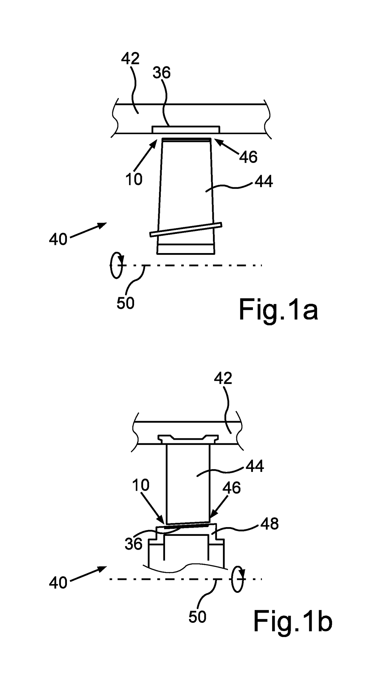
[0030]FIGS. 1a and 1b each show a cross-sectional view of a portion of a turbomachine 40, it being possible for turbomachine 40 to be configured as an engine, for example. In FIG. 1a, an abradable structure 10 is configured on a casing 42, whereas abradable structure 10 in FIG. 1b is configured on a rotor 48 of turbomachine 40. In the present case, abradable structure 10 is formed in one piece and has a carrier element 36 that is adapted for attaching abradable structure 10 to turbomachine 40, thus to casing 42 (FIG. 1a) or to rotor 48 (FIG. 1b).

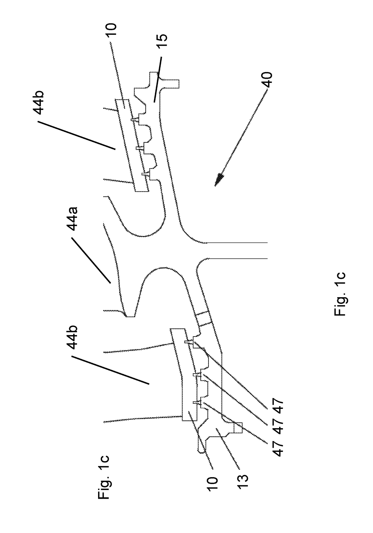
[0031]Turbomachine 40 has a plurality of blade elements, of which a blade element 44 having a blade tip 46 is shown in FIGS. 1a and 1b. FIG. 1a shows blade element 44 as a rotor blade, whereas FIG. 1b shows blade element 44 as a guide vane. During operation of turbomachine 40, blade element 44, formed as a rotor blade in FIG. 1a, rotates about an axis of rotation 50, abradable structure 10 permitting a rubbing in and thus a rubbing contact o...


PUM


Abstract

An abradable structure (10) for a turbomachine (40) that is designed to be at least partially deformed and/or at least partially abraded by at least one abrading element (44, 47) of the turbomachine (40) during operation thereof; the at least one abradable structure (10) being formed at least regionally of structural elements (12, 14, 16, 18) that have a respective polygonal cross section (20, 22) that is oriented in a rub direction (X_A) of the abradable structure (10). The structural elements (12, 14, 16, 18) have a greater extent (Xh, Xr) in the rub direction (X_A) than in a direction of the abradable structure (10) that is orthogonal to the rub direction (X_A). Other aspects of the present invention relate to a turbomachine (40) having an abradable structure (10), as well as to a method for manufacturing an abradable structure (10).

Description

[0001]This claims the benefit of German Patent Application DE 102017209658.6, filed Jun. 8, 2017 and hereby incorporated by reference herein.[0002]The present invention relates to an abradable structure for a turbomachine that is designed to be at least partially deformed and / or at least partially abraded by at least one abrading element of the turbomachine during operation thereof, the at least one abradable structure being formed at least regionally of structural elements having a respective polygonal cross section that is oriented in a rub direction of the abradable structure. Other aspects of the present invention relate to a turbomachine having an abradable structure, as well as to a method for manufacturing an abradable structure.BACKGROUND[0003]Abradable structures of this kind are used, for example, as stator-side abradable coatings on rotor blades of a high-pressure compressor. Abradable structures are frequently used in turbomachines when it is unavoidable, desired or, in ...

Claims


Application Information

Patent Timeline
IPC IPC(8): F01D11/12
CPCF01D11/122F05D2240/55F05D2230/31F05D2250/132F05D2250/131B33Y10/00B33Y80/00F01D11/127F16J15/444F05D2240/11F05D2250/283F05D2250/11F05D2250/314F05D2250/13B22F5/04
Inventor JAKIMOV, ANDREASSCHLOTHAUER, STEFFENLORENZ, BEATRICE
Owner MTU AERO ENGINES GMBH
Why Eureka
Try Eureka