
Image processing apparatus and program

Active Publication Date: 2013-10-31
OKI ELECTRIC IND CO LTD
View PDF1 Cites 4 Cited by
  • Summary
  • Abstract
  • Description
  • Claims
  • Application Information

AI Technical Summary

Benefits of technology

This patent describes a way to improve image processing speed by eliminating the need to create intermediate codes for certain objects. This results in quicker processing for things like gradation patterns, which can make the process more efficient.

Problems solved by technology

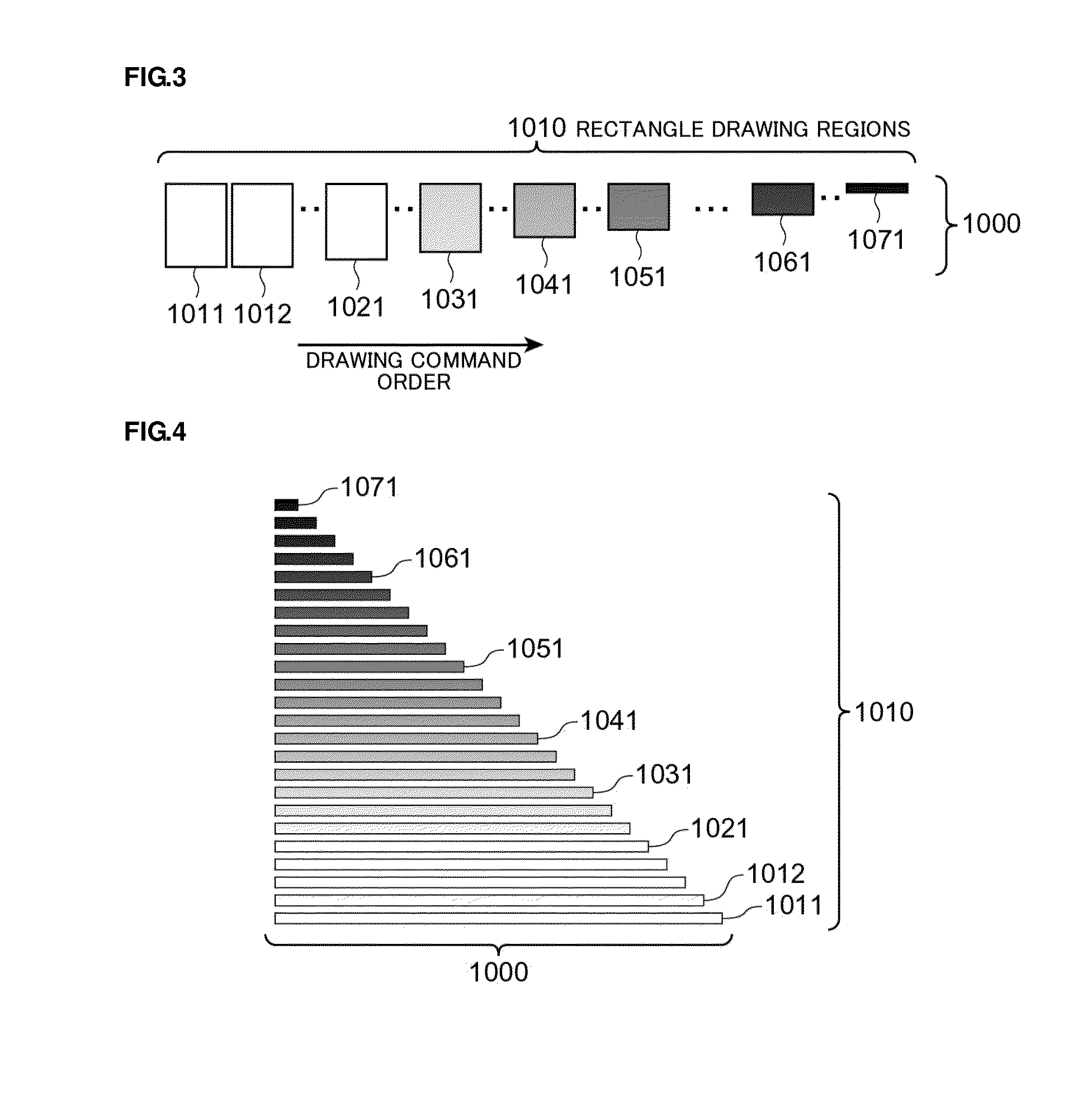
With such an image processing apparatus of a prior art, there raises a problem that the apparatus is unable to perform high speed drawing processing for gradation patterns because of having no adjacent relationship among respective shape drawing objects to be drawn, in a case of using, e.g., a PDL command drawing a gradation pattern upon overlapping shape drawing objects of several tens while changing the density gradually.

Method used


Image

  • Image processing apparatus and program
  • Image processing apparatus and program
  • Image processing apparatus and program

Examples


first embodiment

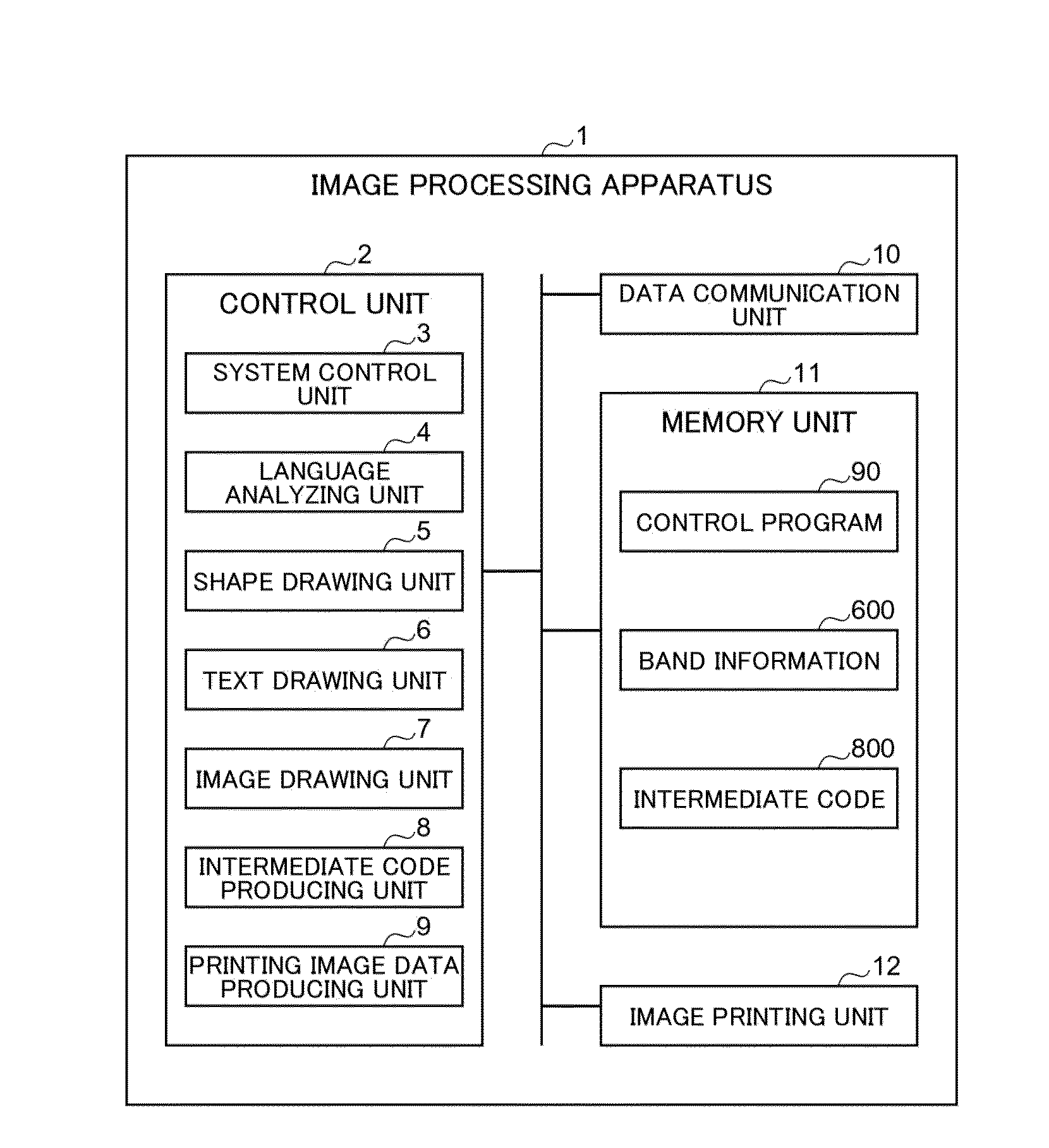
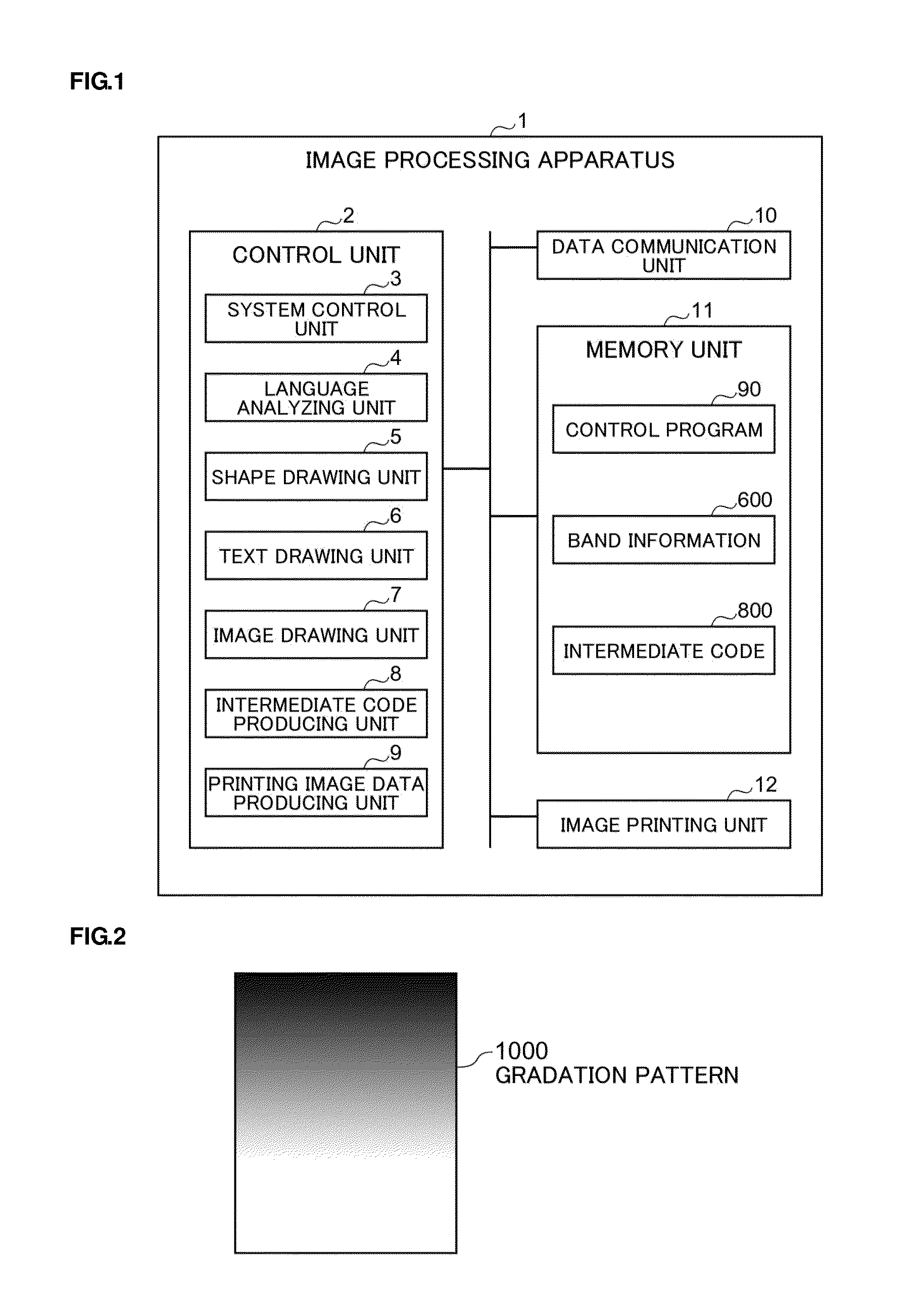
[0032]An image processing apparatus 1 according to the first embodiment (see, FIG. 1) has a feature to draw a gradation pattern 1000 using not a rectangle drawing region 1010 shown in FIG. 4 but a rectangle drawing region 1110 shown in FIG. 10 as a rectangle drawing region structuring each layer of the gradation pattern 1000 (see, FIG. 2).

Structure of the Image Processing Apparatus

[0033]Hereinafter, referring to FIG. 1, the structure of the image processing apparatus 1 according to the first embodiment is described. FIG. 1 is a diagram showing the structure of the image processing apparatus 1 according to the first embodiment. The image processing apparatus is an apparatus drawing various images. It is assumed herein that the image processing apparatus 1 is structured as a page printer.

[0034]As shown in FIG. 1, the image processing apparatus 1 includes a control unit 2, a data communication unit 10, a memory unit 11, and an image printing unit (image forming unit) 12.

[0035]The contr...

second embodiment

[0195]An image processing apparatus 1B, not shown, according to a second embodiment is different in a view for drawing the gradation pattern 100 in use of not the rectangle drawing region 1110 shown in FIG. 10 but the rectangle drawing region 2110 shown in FIG. 14 as the rectangle drawing region forming the gradation pattern 1000 (FIG. 2) in comparison with the image processing apparatus 1 according to first embodiment.

[0196]Hereinafter, the image processing apparatus 1B according to the second embodiment is described in detail. The image processing apparatus 1B according to the second embodiment has the same structure as the image processing apparatus 1 according to the first embodiment (see FIG. 1). The image processing apparatus 1B according to the second embodiment has an intermediate code producing unit 8 operating differently in comparison with the image processing apparatus 1 according to the first embodiment.

[0197]FIG. 12 is a diagram showing operation at a time producing in...


PUM


Abstract

Where plural rectangle drawing objects are provided in an overlapping manner in plural layers each having a different density, an intermediate code producing unit produces plural divisional objects upon dividing a region into prescribed pixel region units at each layer. The divisional object of a lower layer is set as a lower divisional object whereas the divisional object of a layer upper than the lower divisional object is set as an upper divisional object. The invented apparatus omits production of the intermediate code of the lower divisional object completely hiding under the upper divisional object and performs production of the intermediate code of the lower divisional object having a region protruding from the upper divisional object, at each of the prescribed pixel regions from the bottommost layer to the topmost layer.

Description

CROSS REFERENCE TO RELATED APPLICATION[0001]This application claims priority benefits under 35 USC, section 119 on the basis of Japanese Patent Application No. 2012-102375, the disclosure of which is incorporated herein by reference.BACKGROUND OF THE INVENTION[0002]1. Field of the Invention[0003]This invention relates to an image processing apparatus drawing, based on PDL commands, gradation patterns in which plural shape drawing objects each having a density different from each other are overlapped and, more particularly, to an image processing apparatus realizing drawing processing for gradation patters with higher speed. This invention also relates to a program realizing this image processing apparatus.[0004]2. Background of Related Art[0005]Image processing apparatuses have been aiming at higher speed gradation pattern drawing processing by converting respective drawing commands to a drawing command for gradation pattern upon combining the drawing commands in a case where drawin...

Claims


Application Information

Patent Timeline
IPC IPC(8): G06K15/02
CPCG06K15/1872G06K15/1849G06T11/00G06T11/60
Inventor HIRANO, YUJI
Owner OKI ELECTRIC IND CO LTD
Learn More