Anchor structure for electronic card connectors

Inactive Publication Date: 2009-01-15
CONCRAFT HLDG
View PDF7 Cites 1 Cited by
  • Summary
  • Abstract
  • Description
  • Claims
  • Application Information

AI Technical Summary

Benefits of technology

[0008]The primary object of the present invention is to solve the aforesaid disadvantages. The present invention provides a fastening element that does not need rivet coupling. Production time can be reduced. The fastening element has an anchor structure mating a body to form a secure coupling that is not too tight or too loose. And it can be flexibly controlled to achieve a desired fitness.

Problems solved by technology

Their quality not only affects the reliability of electric current and signal transmission, also impacts operation quality of the entire electronic equipment.
Such a structure tends to create shaking of the insulation body.
It is not steady or reliable, and not desirable for soldering the connector pins.
Dislocation easily occurs to the insulation body under forces during insertion or unplugging of external elements.
And the pins of the connector are prone to loosen off and signal transmission could be impacted.
However the conventional technique previously discussed still has drawbacks, notably:1. It requires a riveting operation in the fabrication process.
More production time is needed.2. Riveting operation has to be performed under a huge force that easily damages the structure of the body.
On the other hand, to do the riveting operation at a smaller force does not form a strong enough binding, and the body is easily loosened that could affect the quality of signal transmission.3. Riveting operation forms a fixed coupling on the holding orifice.
It cannot be disassembled and the fitness cannot be controlled.

Method used


Image

  • Anchor structure for electronic card connectors
  • Anchor structure for electronic card connectors
  • Anchor structure for electronic card connectors

Examples


Embodiment Construction

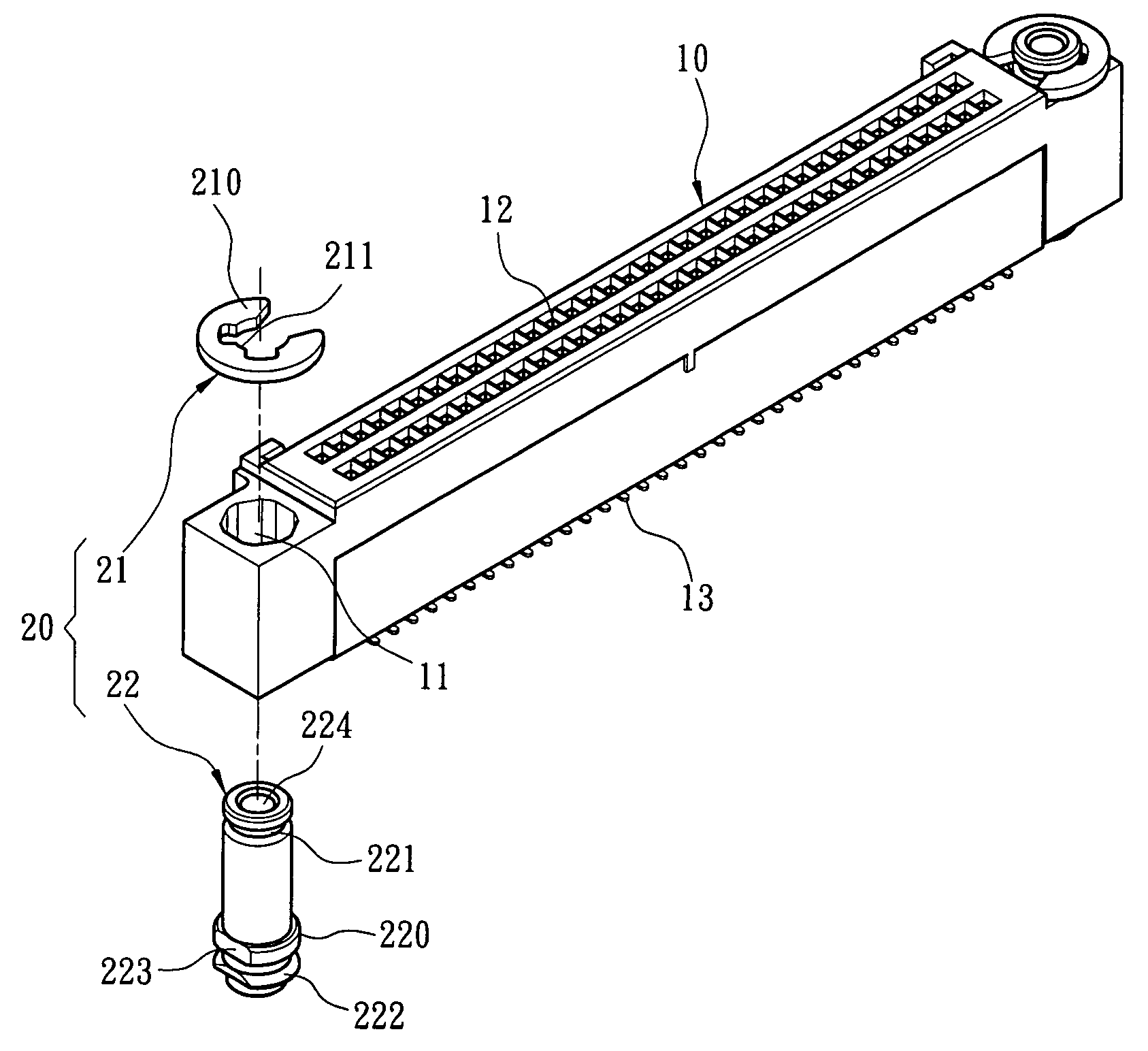
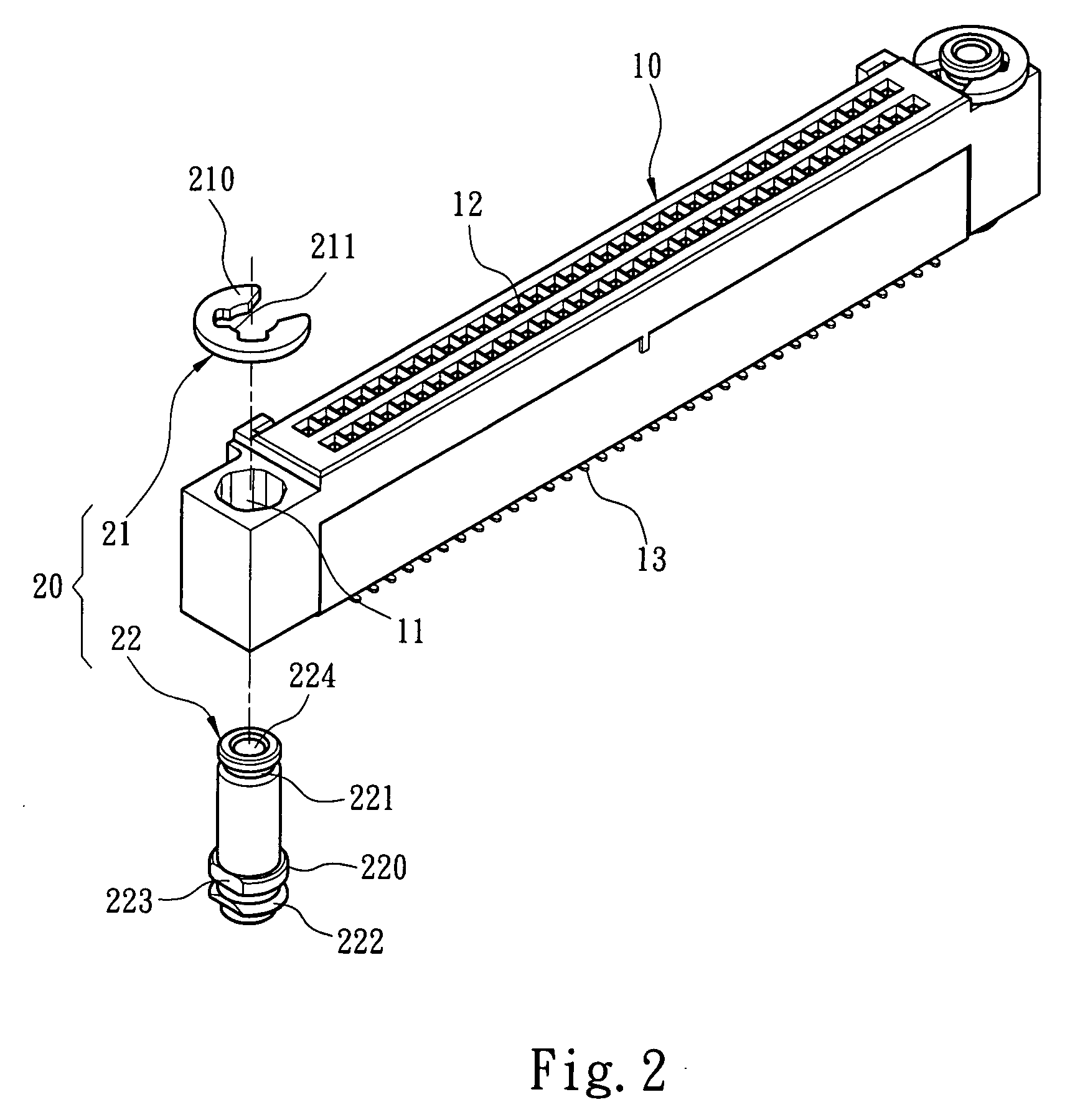
[0016]Please refer to FIGS. 2, 3 and 4, the anchor structure for electronic card connectors according to the invention includes a body 10 and a fastening element 20. The body 10 has a holding bore 11 to hold the fastening element 20. The fastening element 20 includes an anchor member 21 and an anchor seat 22. The anchor member 21 and anchor seat 22 have respectively an extended portion 210 and 220 that have an outer diameter greater than the fastening element 20. The anchor member 21 has a first anchor portion 211. The fastening seat 22 has a corresponding second anchor portion 221. In an embodiment of the invention the first and second anchor portions 211 and 221 are a C-shaped clip and a groove that mate each other so that they can be coupled or disengaged with each other.

[0017]In an embodiment of the invention, the anchor structure is coupled with a connector 30 and installed at a desired location on a circuit board 40. The connector 30 is inserted into an orifice 12 to be connec...


PUM


Abstract

An anchor structure for electronic card connectors to provide flexible control of fitness includes a fastening element and a body which has a holding bore at two ends. The fastening element has an anchor member and an anchor seat. The anchor member and the anchor seat have respectively an extended portion formed at an outer diameter slightly greater than the fastening element. The anchor member has a first anchor portion. The anchor seat has a second anchor portion. The first and second anchor portions can be coupled together or disengaged with each other.

Description

FIELD OF THE INVENTION[0001]The present invention relates to an anchor structure for electronic card connectors and particularly to an anchor structure that can flexibly control fitness of electronic card connectors.BACKGROUND OF THE INVENTION[0002]The progress of electronic information products advances rapidly these days. Demands of users on electronic products are higher. Utilization scope of the electronic products is expanded constantly. Function of electronic products such as computers, mobile phones, digital cameras and the like also increases. The auxiliary function also is enhanced. The peripheral electronic circuits and connection terminals become more complex and versatile. The connectors generally mean connection elements and their accessories used to transmit electronic signals and power supply. They are indispensable elements in the electronic information products. Their quality not only affects the reliability of electric current and signal transmission, also impacts ...

Claims


Application Information

Patent Timeline
IPC IPC(8): E01B9/12
CPCH01R12/716H01R12/7029
Inventor LAI, SHIH-CHIALEE, KUO-CHI
Owner CONCRAFT HLDG
Why Eureka
Try Eureka