Supercharge Your Innovation With Domain-Expert AI Agents!

Liquid ejecting head and liquid ejecting apparatus

Active Publication Date: 2018-12-20
SEIKO EPSON CORP
View PDF7 Cites 2 Cited by
  • Summary
  • Abstract
  • Description
  • Claims
  • Application Information

AI Technical Summary

Benefits of technology

The invention provides a liquid ejecting head and apparatus that can prevent the flexible cable from detaching during installation due to warping of components.

Problems solved by technology

The liquid ejecting head formed as such may be subject to warping due to, for example, differences between the coefficients of thermal expansion of components.
In the case where an installation portion of the flexible cable, which is constituted by electric contacts, extends in the longitudinal direction of the liquid ejecting head, warping of the components in the longitudinal direction may cause detachment of the flexible cable at the installation portion, which poses a problem.
However, the above configuration of using correction plates to suppress the liquid ejecting head from warping has a problem in that the number of parts increases and provision of the correction plates poses restrictions on the components in terms of their dimensions, shape, or the like.
As a result, even when the common member and other components that extend in the first direction warp, detachment of the flexible cable from the head substrate does not readily occur in the fixation region, in other words, in an installation portion at which the flexible cable is installed to the corresponding head substrate.
As a result, even when the common member and other components that extend more in the first direction warp in the first direction, detachment of the flexible cable at the installation portion does not readily occur.
As a result, when the common member and other components that extend in the first direction warp in the first direction, detachment of the flexible cable from the circuit substrate at the installation portion does not readily occur.
As a result, even when the common member and other components that extend more in the first direction warp in the first direction, detachment of the flexible cable at the installation portion does not readily occur.
As a result, when the common member, the circuit substrate, and other components that extend in the first direction warp in the first direction, detachment of the flexible cable from the circuit substrate does not readily occur at the installation portion.
As a result, detachment of the flexible cable from the circuit substrate does not readily occur at the installation portion.
As a result, the holder member is not easily subject to deformation, such as warping or twisting.
According to this configuration, the difference in the coefficient of thermal expansion tends to cause the holder member and the common member to warp.
The flexible cables tend to generate heat.
The thickness of the conductors at the other end of each flexible cable is larger than that of the conductors at the one end, thereby reducing the resistance of the conductors.

Method used


Image

  • Liquid ejecting head and liquid ejecting apparatus
  • Liquid ejecting head and liquid ejecting apparatus
  • Liquid ejecting head and liquid ejecting apparatus

Examples


Embodiment Construction

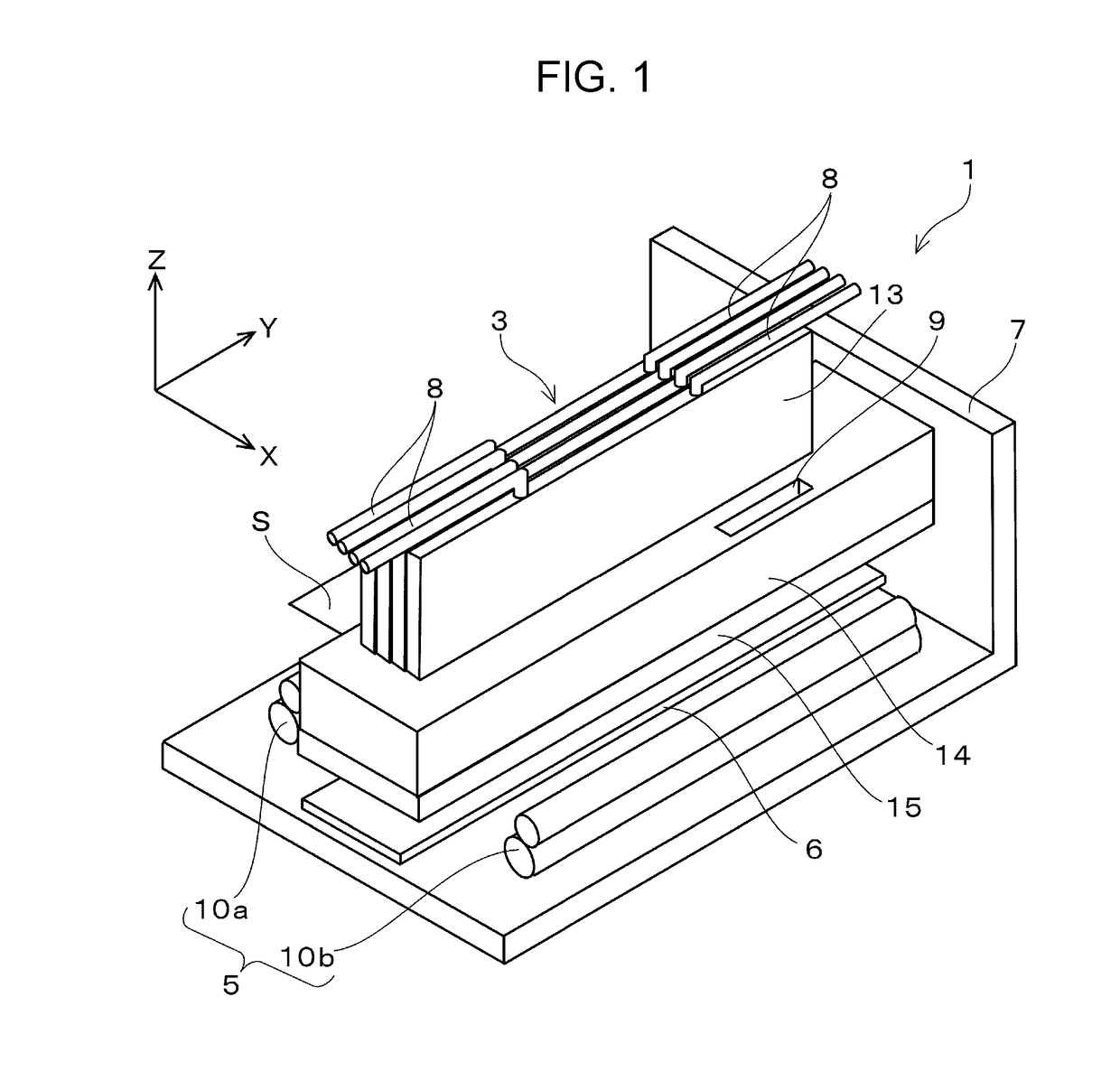
[0060]Exemplary embodiments will be described with reference to the accompanying drawings. Note that although various limitations will be included in the description of exemplary embodiments in order to describe preferred examples of the invention, such particular configurations should not be construed as limiting the scope of the invention unless expressly stated otherwise. Also note that the following description is based, by way of example, on an ink jet type printer (hereinafter referred to as “printer 1”) in which an ink jet type recording head (hereinafter simply referred to as “recording head 3”), which is a type of liquid ejecting head, is mounted. The ink jet type printer serves as a liquid ejecting apparatus according to the invention.

[0061]A structure of the printer 1 will be described with reference to FIG. 1. Note that in the drawings, the X direction (which corresponds to a second direction according to the invention), the Y direction (which corresponds to a first dire...


PUM


Abstract

A liquid ejecting head includes head units each of which includes a corresponding head substrate and ejects liquid, flexible cables each of which has one end connected to the corresponding head substrate, and a common member including the head units that are fixed thereto. In the liquid ejecting head, when a first direction, a second direction, and a third direction are directions that orthogonally intersect each other and the common member is placed on a virtual surface defined by the first direction and the second direction and has a thickness extending in the third direction, the common member extends more in the first direction than in the second direction. In addition, a fixation region in which each of the flexible cables and the corresponding head substrate are fixed to each other extends more in the second direction than in the first direction when viewed in the third direction.

Description

BACKGROUND1. Technical Field[0001]The present invention relates to a liquid ejecting head equipped with a plurality of head units that eject liquid from nozzles, and to a liquid ejecting apparatus equipped with the liquid ejecting head.2. Related Art[0002]An example of a liquid ejecting head is an ink jet type recording head that is used in an image recording apparatus, such as an ink jet type recording apparatus. In recent years, a liquid ejecting head that can cause a small amount of liquid to strike precisely at a predetermined position has been advantageously applied to various manufacturing apparatuses. Examples of such apparatuses include a display manufacturing apparatus that manufactures color filters for liquid crystal displays or the like, an electrode forming apparatus that forms electrodes for organic electro luminescence (EL) displays, field emission displays (FED), or the like, and a chip manufacturing apparatus that manufactures biochips. The recording head for the im...

Claims


Application Information

Patent Timeline
IPC IPC(8): B41J2/14
CPCB41J2/1433B41J2/01B41J2002/14491B41J2202/20B41J2/14233B41J2002/14241B41J2/14072
Inventor TAKINO, FUMIYAMATSUOKA, HIRONORI
Owner SEIKO EPSON CORP
Features
  • R&D
  • Intellectual Property
  • Life Sciences
  • Materials
  • Tech Scout
  • Unparalleled Data Quality
  • Higher Quality Content
  • 60% Fewer Hallucinations
Learn More