Detachable slat angle adjustment mechanism

Inactive Publication Date: 2018-12-20
SHEEN WORLD TECH CORP
View PDF5 Cites 4 Cited by
  • Summary
  • Abstract
  • Description
  • Claims
  • Application Information

AI Technical Summary

Benefits of technology

[0004]The present invention has been accomplished under the circumstances in view. It is the main object of the present to provide a detachable slat angle adjustment mechanism for window blind, w

Problems solved by technology

However, as the worm shaft and the worm wheel have been installed in the casing in the factory, they do not allow the consumer to assemble the slat angle adjustment mechanism after purchase, so the worm shaf

Method used


Image

  • Detachable slat angle adjustment mechanism
  • Detachable slat angle adjustment mechanism
  • Detachable slat angle adjustment mechanism

Examples


Example

[0014]The present invention will now be described in detail with reference to the accompanying drawings, in which the directional terms of “top”, “bottom”, “left”, “right”, “inside”, “outside” are terms of benchmark description in the normal use but not intended for use to limit the scope of the intention.

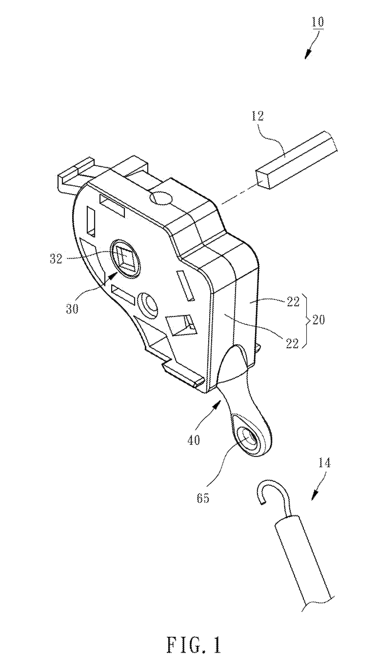
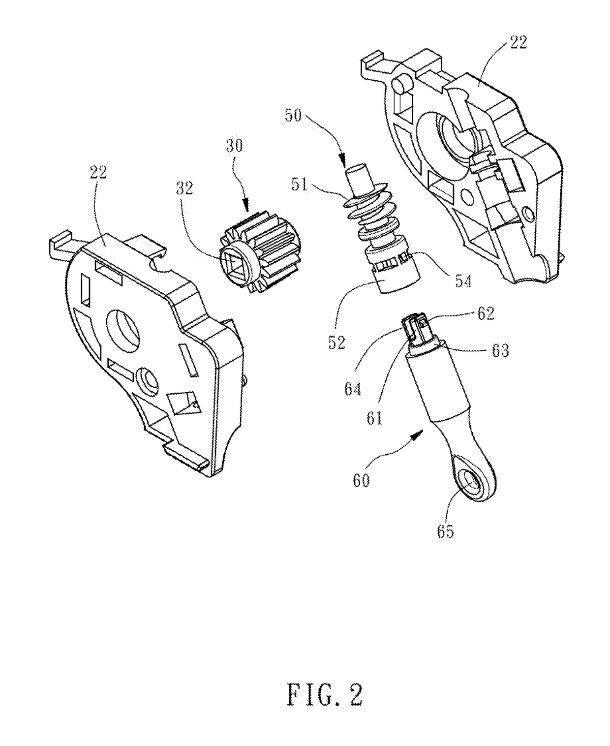
[0015]Referring to FIG. 1 and FIG. 2, a detachable slat angle adjustment mechanism 10 in accordance with the present invention is shown. The detachable slat angle adjustment mechanism 10 comprises a casing 20, a worm wheel 30, and a worm shaft set 40.

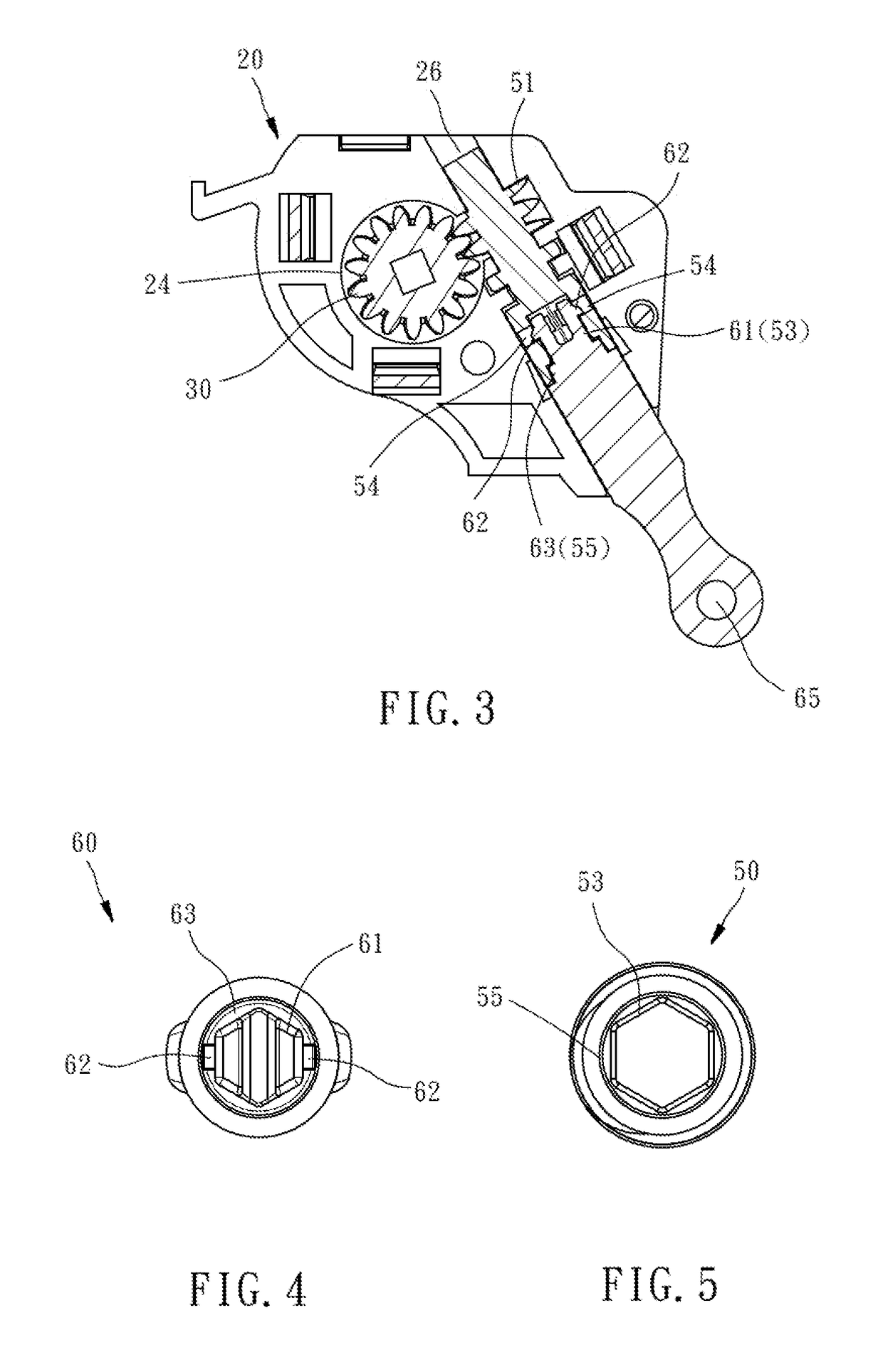
[0016]The casing 20 comprises two half shells 22 fastened together, a first mounting through hole 24 horizontally cutting through opposing left and right sides of the two half shells 22, and a second mounting through hole 26 obliquely cutting through opposing top and bottom sides of the two half shells 22.

[0017]The worm wheel 30 is rotatably mounted in the first mounting through hole 24 of the casing 20, comprising a rectangular coupli...


PUM


Abstract

A detachable slat angle adjustment mechanism includes a casing, a worm wheel rotatably mounted in the casing, and a worm shaft set including a first shaft member and second shaft member. The first shaft member is rotatably mounted in the casing and includes a worm meshed with the worm wheel and a coupling portion with an axle hole axially defined therein and two opposing positioning hole connected to the axle hole. The second shaft member has a mounting axle axially extended from a top end thereof and detachably insertable into the axle hole of the first shaft member, two positioning protrusions respectively protruded from the outer perimeter of the mounting axle and detachably engageable into the respective positioning holes of the first shaft member, and an opposing bottom end that suspends outside the casing after connection of the mounting axle to the axle hole of the first shaft member.

Description

BACKGROUND OF THE INVENTION1. Field of the Invention[0001]The present invention relates to window blind technology, and more particularly to a detachable slat angle adjustment mechanism for window blind.2. Description of the Related Art[0002]A conventional slat angle adjustment mechanism for adjusting the angle of the slats of a window blind generally comprises a casing, a worm wheel, and a worm shaft. The casing is mounted in the top rail of the window blind. The worm wheel is rotatably mounted in the casing. The worm shaft has a worm located at one end thereof and inserted into the inside of the casing and meshed with the worm wheel, and an opposite end thereof extended out of the casing and suspended outside the top rail for the hooking of a rotary handle that is biasable by the user to rotate the worn shaft and the worm wheel, causing a connected transmission member to bias the slats of the window blind.[0003]However, as the worm shaft and the worm wheel have been installed in t...

Claims


Application Information

Patent Timeline
IPC IPC(8): F16D1/108E06B9/322F16H1/16
CPCF16D1/108E06B9/322F16H1/16F16D2001/102E06B9/307
Inventor CHEN, PO-YU
Owner SHEEN WORLD TECH CORP
Why Eureka
Try Eureka