Transformers and winding units thereof

a transformer and winding unit technology, applied in the direction of transformer/inductance details, coils, inductances, etc., can solve the problems of shortening affecting the peripheral electronic device, and affecting the yield of the transformer, so as to facilitate guidance, facilitate mounting, and potentially increase the life of the transformer

Active Publication Date: 2008-10-21
DELTA ELECTRONICS INC
View PDF5 Cites 20 Cited by
  • Summary
  • Abstract
  • Description
  • Claims
  • Application Information

AI Technical Summary

Benefits of technology

[0009]The winding unit has a non-winding portion and a winding portion with a conductive wire wound thereon. The conductive wire, such as a triple-insulated wire or an enamel-insulated wire, is wound substantially on the same plane to reduce dimension of the transformer. Specifically, the winding and the non-winding portions are disposed on different planes to form a space therebetween. The winding portion comprises a first joining portion and at least a rib. When joining the winding unit to the bobbin, the bobbin can be engaged by the first joining portion easily, wherein the rib and the bobbin are press-fitted in order to eliminate excessive strain and to prevent sliding therebetween.
[0013]The winding units of the transformer can be easily mounted on the bobbin, wherein turns of the wire on each winding unit can be appropriately adjusted for various applications. Moreover, each of the bobbin and the winding units comprises a recess and a guiding slope in order to facilitate guidance and protect the wire, so that unintentional damage of the wire during the assembling is prevented, and life of the transformer is potentially increased.
[0014]Transformers of the present invention have smaller dimensions than conventional transformers to prevent excess height and to save considerable space for other electronic devices. In some embodiments, each of the winding units comprises a rib press-fitted to the bobbin in order to prevent sliding therebetween and to simplify winding assembly of the transformer. Moreover, each of the bobbins, the plates and the insulating sheets comprises a joining portion corresponding to each other to provide easy assembly and firm connection of the bobbin.
[0015]Unlike conventional transformers using tapes, the invention provides a transformer having a sandwiched structure to prevent inductance leakage and to improve heat dissipation efficiency.

Problems solved by technology

Moreover, when windings are not appropriately arranged, the transformer can fail and influence yield.
Further, the insulating tapes may obstruct heat dissipation, shortening life of the transformer and adversely affecting peripheral electronic devices.

Method used


Image

  • Transformers and winding units thereof
  • Transformers and winding units thereof
  • Transformers and winding units thereof

Examples


first embodiment

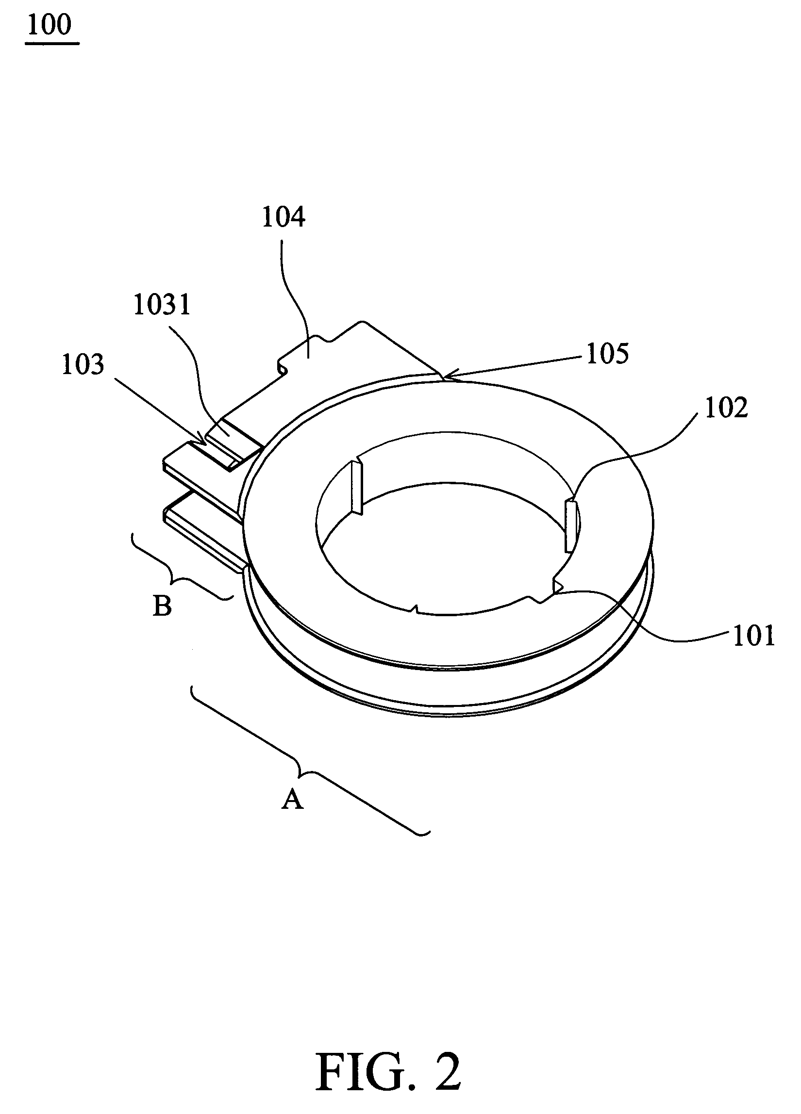
[0027]FIG. 2 shows a first winding unit 100 having a winding portion A and a non-winding portion B. A conductive wire, such as a triple-insulated wire (not shown), is wound around the winding portion A substantially on the same plane in order to facilitate height reduction of transformer 200 shown in FIG. 3A.

[0028]In FIG. 2, the winding portion A and the non-winding portion B respectively have end surfaces situated on different horizontal planes. The winding portion A comprises a first joining portion 101 and at least a rib 102. When assembling the first winding unit 100 to a bobbin, such as the bobbin 202 shown in FIG. 3C and will be described thereafter, the bobbin is engaged through the first joining portion 101, wherein the rib 102 and the bobbin are press-fitted to eliminate excessive strain and to prevent sliding therebetween.

[0029]The non-winding portion B comprises at least a recess 103 and a protrusion 104. The recess 103 has a slope 1031 to receive the conductive wire. The...

second embodiment

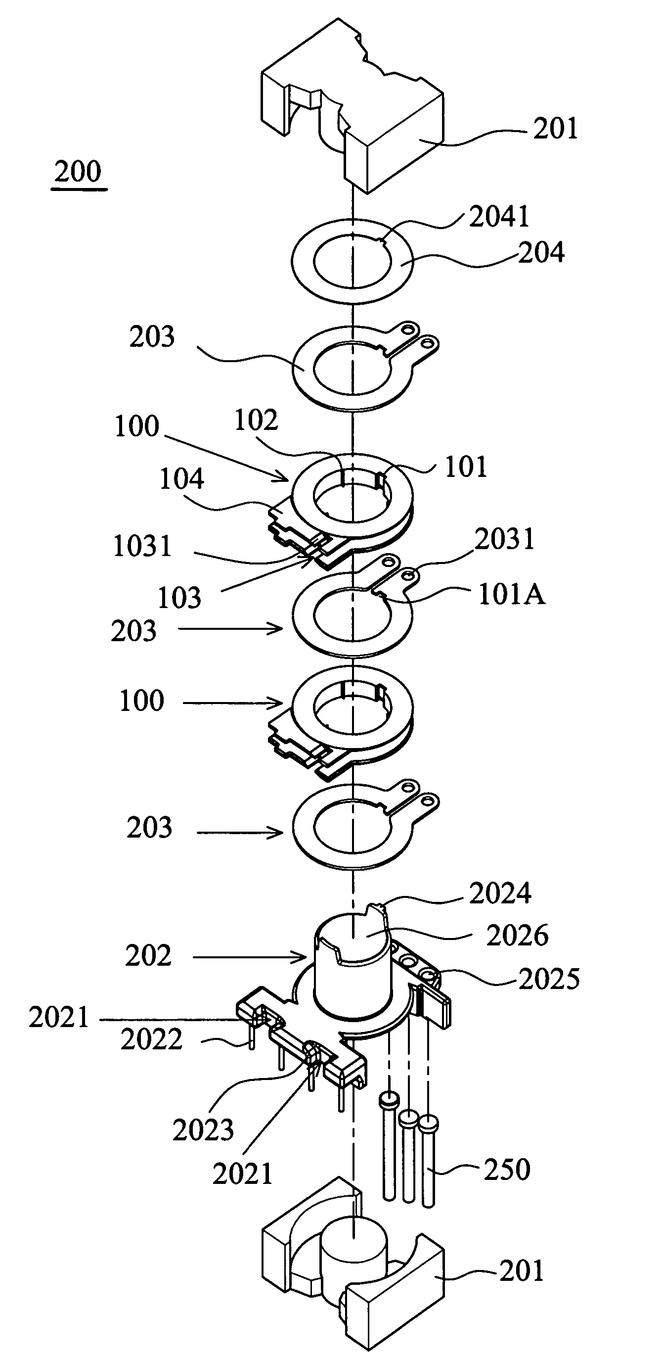
[0034]FIG. 6B is an exploded diagram of a transformer 500. The transformer 500 primarily comprises a ferromagnetic core unit 201 formed by two cores, a bobbin 402, at least a first winding unit 100, at least a second winding unit 300, and at least a plate 203A. Elements corresponding to the ferromagnetic core unit 201 and the first winding unit 100 of FIGS. 3B and 6B share the same reference numerals, and explanation thereof is omitted for simplification of the description.

[0035]FIG. 4 is a schematic diagram of the second winding unit 300. The second winding unit 300 has a winding portion C and a non-winding portion D. A conductive wire, such as a triple-insulated wire or an enamel-insulated wire (not shown), is wound around the winding portion C substantially on the same plane to facilitate dimension reduction of the transformer. As shown in FIG. 4, the winding portion C comprises an abutting portion 301 and at least a recess 303. The recess 303 has a slope 3031 to receive the cond...


PUM

PropertyMeasurementUnit
heightaaaaaaaaaa
voltageaaaaaaaaaa
input voltageaaaaaaaaaa

Abstract

Transformers are provided. A transformer comprises a ferromagnetic core unit; a bobbin coupled with the ferromagnetic core unit; at least a winding unit as a primary winding and at least a plate as a secondary winding. Also, some of the winding units can act as a secondary winding. At least a winding unit and at least a plate are alternatively stacked in a staggered manner. A conductive wire is wound around the winding unit.

Description

BACKGROUND OF THE INVENTION[0001]1. Field of the Invention[0002]The invention relates in general to transformers and in particular to transformers having winding units.[0003]2. Description of the Related Art[0004]Transformers are widely applied in electronic devices to transform drive voltage from circuits, such as conventional power transformers to lower voltage or step-up transformers used in monitors to raise an operating voltage from circuits. Conventional transformers can be made to measure for various types, wherein miniaturization is usually a significant requirements.[0005]Generally, a transformer requires at least a primary winding and a secondary winding. The primary winding receives an input voltage, and the secondary winding generates an output voltage by electromagnetic induction from the primary winding. Function of the transformer depends on turn ratio of the primary and secondary windings.[0006]Referring to FIG. 1, a conventional transformer 10 primarily comprises a ...

Claims


Application Information

Patent Timeline
Patent Type & Authority Patents(United States)
IPC IPC(8): H01F27/30
CPCH01F27/2866H01F17/043H01F27/325H01F2005/043
Inventor CHEN, YU-CHANCHENG, KAI-YUANCHENG, I-CHITSAI, HSIN-WEIFENG, WEN-PINCHOU, HENG-CHENGLIAO, KAO-TSAIWU, YI-FAN
Owner DELTA ELECTRONICS INC
Why Eureka
Try Eureka