Sensor cleaning system for an autonomous robot device, base station and corresponding method

Active Publication Date: 2015-07-16
HONDA RES INST EUROPE
View PDF4 Cites 22 Cited by
  • Summary
  • Abstract
  • Description
  • Claims
  • Application Information

AI Technical Summary

Benefits of technology

[0017]Providing a first position for cleaning at the base station which is spatially different from a second position at the base station for charging the autonomous robot device is advantageous, as the sensor of the autonomous robot device then may not necessarily be cleaned each time the autonomous robot device arrives at the base station for charging its energy storage. Further the operation of multiple autonomous robot devices with only one base station may be more easily organized when providing different sensor cleaning positions and recharging positions at a base station. Providing different positions for charging also enables to separate technical requirements for charging the energy storage (rechargeable battery or accumulator) of the autonomous robot device which is advantageously executed with the autonomous robot device remaining in an entirely static position with respect to the base station on one hand. On the other hand cleaning the sensor means of the autonomous robot device by moving the autonomous robot device to generate a relative movement of the sensor means with respect to the cleaning means to effect the cleaning of the sensor means is advantageously executed when moving the autonomous robot device in a suitable manner towards or from the first position at the base station.
[0018]In an advantageous embodiment of the invention the cleaning means is configured to effect a brushing or wiping movement across the sensor means when the aut

Problems solved by technology

Therefore the complexity of the autonomous robot device and the complexity of its operation is further increased.
Hence the technical problem of providing an autonomous robot device with a robust, capable and cost effective sensor cleaning mechanism arises.
The cleaning means of the cleaning system further dispenses with the need for providing the single dynamic portion of the system represented by the autonomous robot device with any further mechanical

Method used


Image

  • Sensor cleaning system for an autonomous robot device, base station and corresponding method
  • Sensor cleaning system for an autonomous robot device, base station and corresponding method
  • Sensor cleaning system for an autonomous robot device, base station and corresponding method

Examples


Example

[0038]The following description and explanation refers to an autonomous lawn mower as a typical example of an autonomous robot device according to the invention. Of course it is evident that any details which are discussed in the following may also be used in conjunction with other autonomous garden tools or any autonomous robot device employing sensors. Such robot device forms a system with a base station.

[0039]In particular the autonomous robot device may be one of a cleaning robot, vacuum cleaner or window cleaner or even any propelled (e.g. electrically propelled) vehicle operating from a base station.

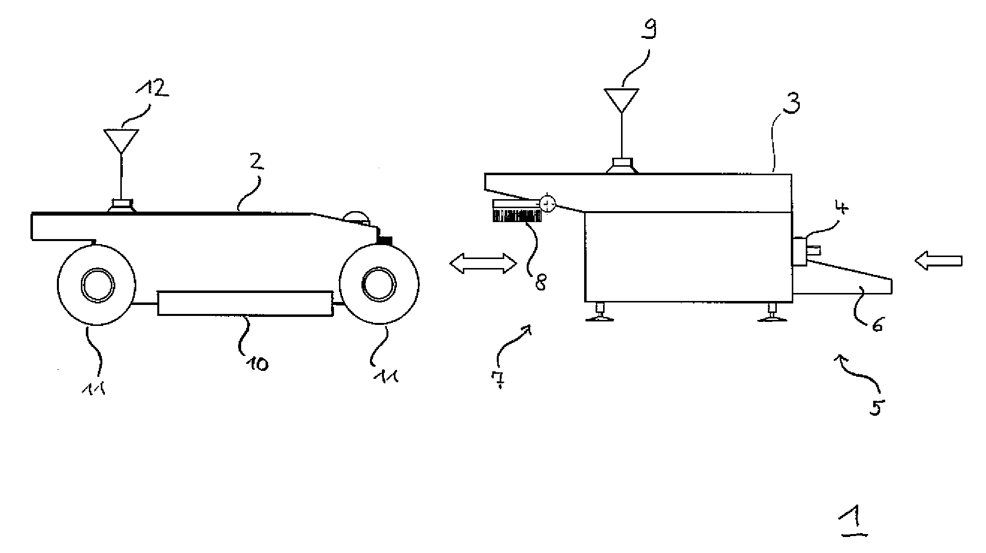
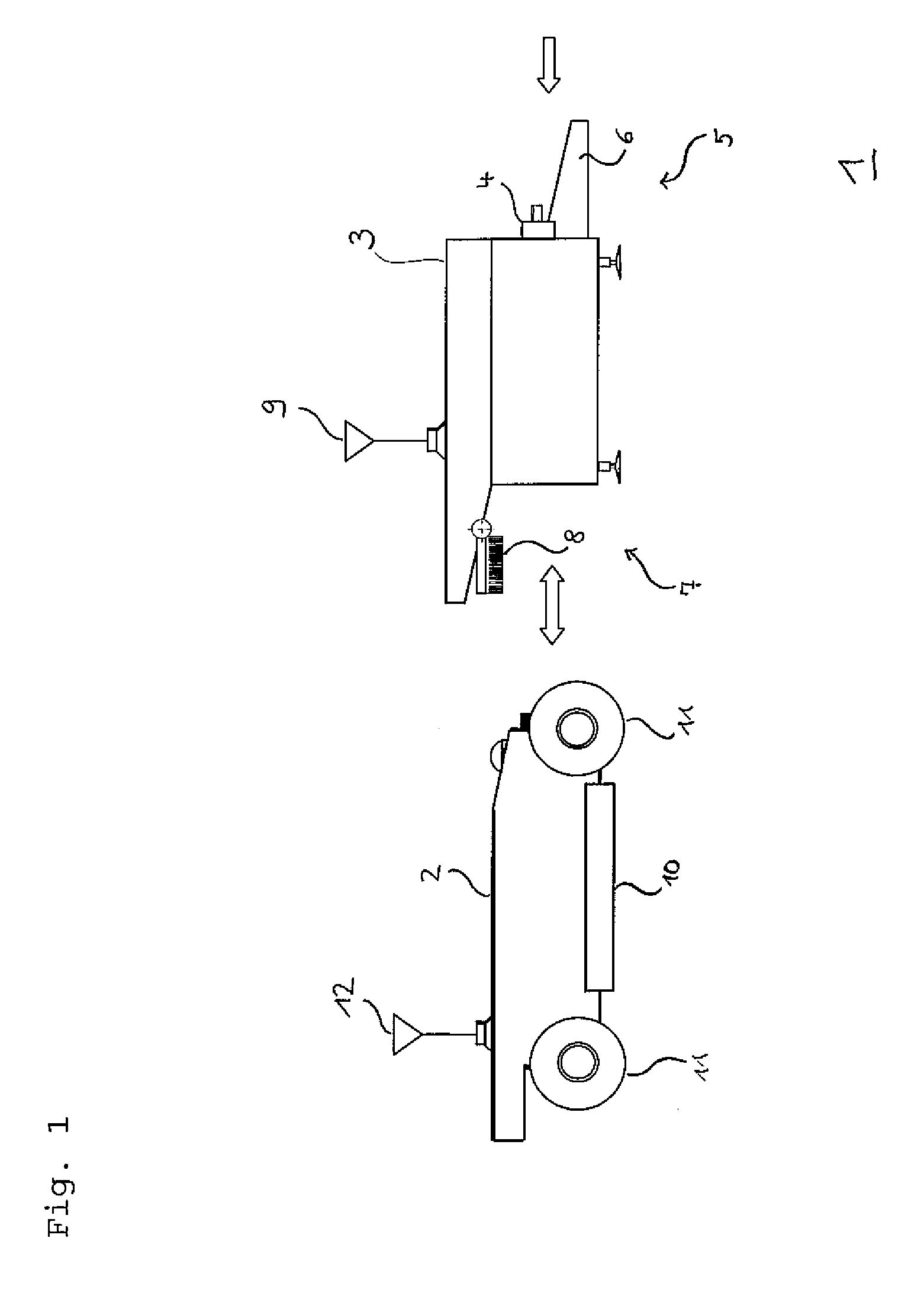
[0040]FIG. 1 shows a system 1 including an autonomous robot device and its base station 3 according to an embodiment of the invention. The autonomous robot device 2 in the FIG. 1 and the base station 3 both form part of the system 1. The base station 3 is specifically adapted to recharge the energy storage means or battery of the autonomous robot device and includes for this purpos...


PUM


Abstract

The inventive system comprises an autonomous robot device, a base station and a method operating the same. The autonomous robot device includes a sensor means, e.g. an optical sensor, and a propulsion means. The base station includes a cleaning means specifically adapted for cleaning the sensor means of the autonomous robot device. In a preferred embodiment the propulsion means of the autonomous robot device is configured to move the autonomous robot device in a manner suitable to generate a relative movement of the autonomous robot device with respect to the passive cleaning means arranged at the stationary base station to effect the cleaning of the sensor means of the autonomous robot device.

Description

BACKGROUND[0001]1. Field[0002]The present invention relates to a system, a base station and a method for cleaning a sensor of an autonomous robot device like an autonomous garden device. In particular the present invention relates to a base station for an autonomous lawn mower and a system for cleaning an optical sensor mounted on the autonomous lawn mower. The present invention further relates to a base station for an autonomous robot device and a method for cleaning the sensor of the autonomous robot device.[0003]Autonomous or robotic devices, e.g. autonomous lawn mowers, are an increasing market. In many approaches of autonomous lawn mowers the working area is delimited by an electric border wire generating an electromagnetic field. This electromagnetic field is used by the autonomous device to identify the assigned working area, and to find a docking station or base station for recharging its energy storage. For avoiding static or dynamic obstacles that are not indicated by the ...

Claims


Application Information

Patent Timeline
IPC IPC(8): G05D1/02B08B1/00A01D34/00B08B3/02
CPCG05D1/0225B08B3/02B08B1/006Y10S901/46A01D34/008Y10S901/01Y10S901/30B08B1/002G05D2201/0215B60S3/04
Inventor EINECKE, NILSFRANZIUS, MATHIASSENDHOFF, BERNHARD
Owner HONDA RES INST EUROPE
Why Eureka
Try Eureka