
Semiconductor structure and method for manufacturing the same

Active Publication Date: 2015-05-28
INST OF MICROELECTRONICS CHINESE ACAD OF SCI
View PDF5 Cites 8 Cited by
  • Summary
  • Abstract
  • Description
  • Claims
  • Application Information

AI Technical Summary

Benefits of technology

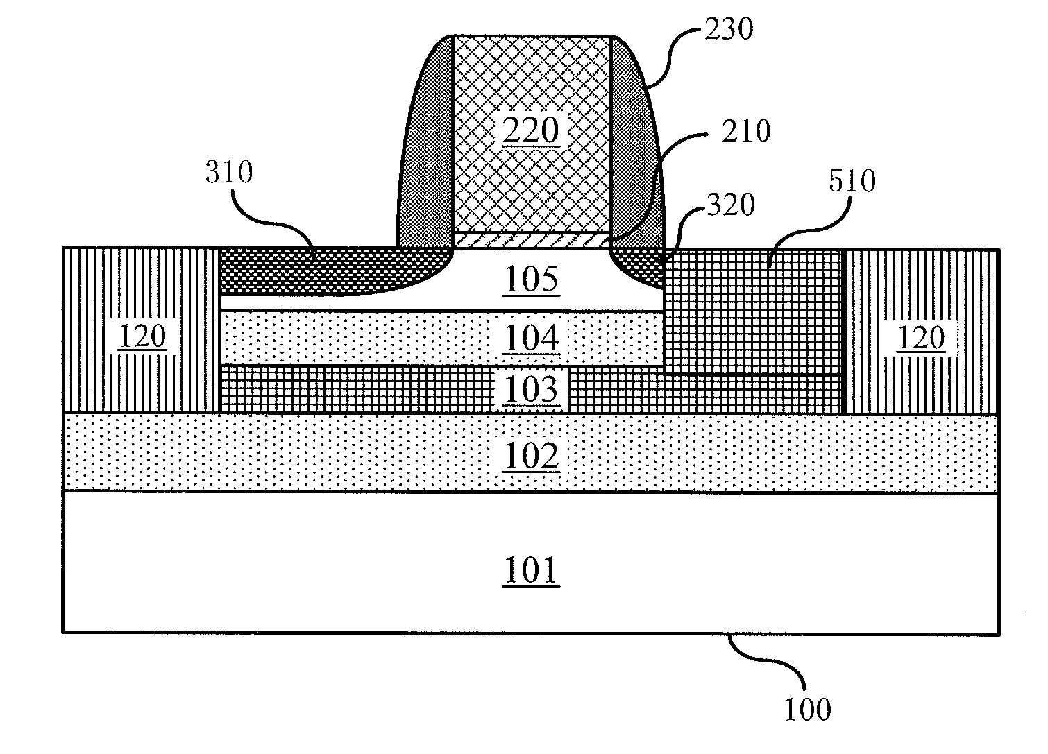
The present invention provides a semiconductor structure and a method for manufacturing it, where a buried ground layer is electrically connected to the source region, without the need for an independent contact for the buried ground layer. This saves device area and simplifies the manufacturing process. Additionally, the invention improves device performance by enhancing control capabilities over threshold voltages and suppressing short-channel effects. In summary, this invention provides a more efficient and cost-effective semiconductor structure.

Problems solved by technology

Traditional planar bulky Si CMOS technology cannot any more boost improvement in device performance and decrease power consumption at the meantime of improving integrity of circuits.
Consequently, device parameters fluctuate randomly and the threshold voltage cannot be scaled down proportionally, which further brings limits on enhancement of whole device performance.
In technology node of 45 nm and below, dramatically soaring short-channel effects also raise difficulties of further scaling down devices proportionally.
However, circuit area has been increased inevitably due to introduction of back gate contact and relevant wiring, thereby increasing manufacturing cost.
Therefore, for UTBB SOI devices, how to find a balance between optimal device performance and costs has now become a critical problem that is waiting for a solution.

Method used


Image

  • Semiconductor structure and method for manufacturing the same
  • Semiconductor structure and method for manufacturing the same
  • Semiconductor structure and method for manufacturing the same

Examples


Embodiment Construction

[0018]Embodiments of the present invention are described at length below, wherein examples of the embodiments are illustrated in the drawings, in which same or similar reference signs throughout denote same or similar elements or elements have same or similar functions. It should be appreciated that embodiments described below in conjunction with the drawings are illustrative, and are provided for explaining the prevent invention only, thus shall not be interpreted as a limit to the present invention. Various embodiments or examples are provided here below to implement different structures of the present invention. To simplify the disclosure of the present invention, descriptions of components and arrangements of specific examples are given below. Of course, they are only illustrative and not limiting the present invention. Moreover, in the present invention, reference numbers and / or letters may be repeated in different examples. Such repetition is for purposes of simplicity and cla...


PUM


Abstract

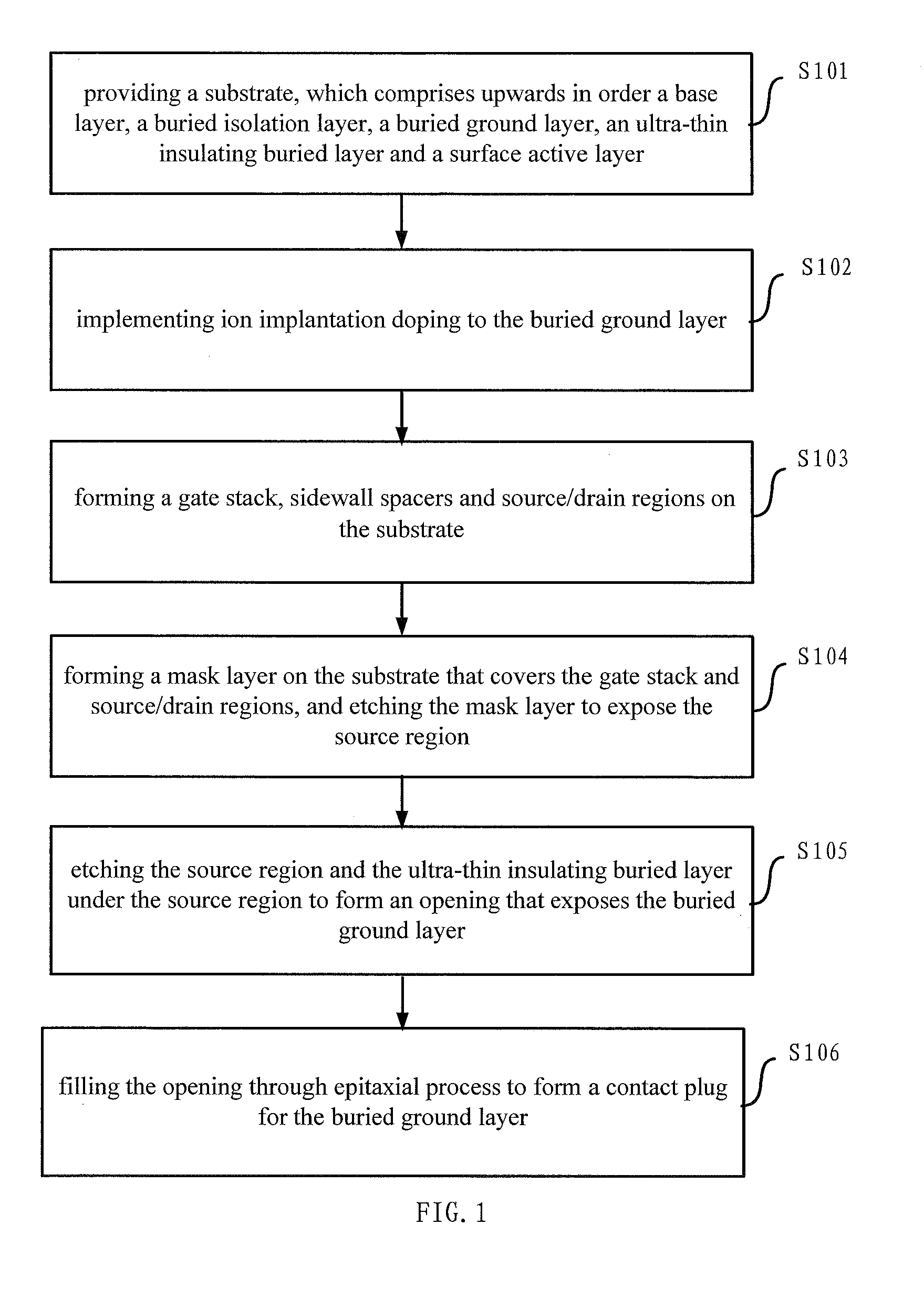
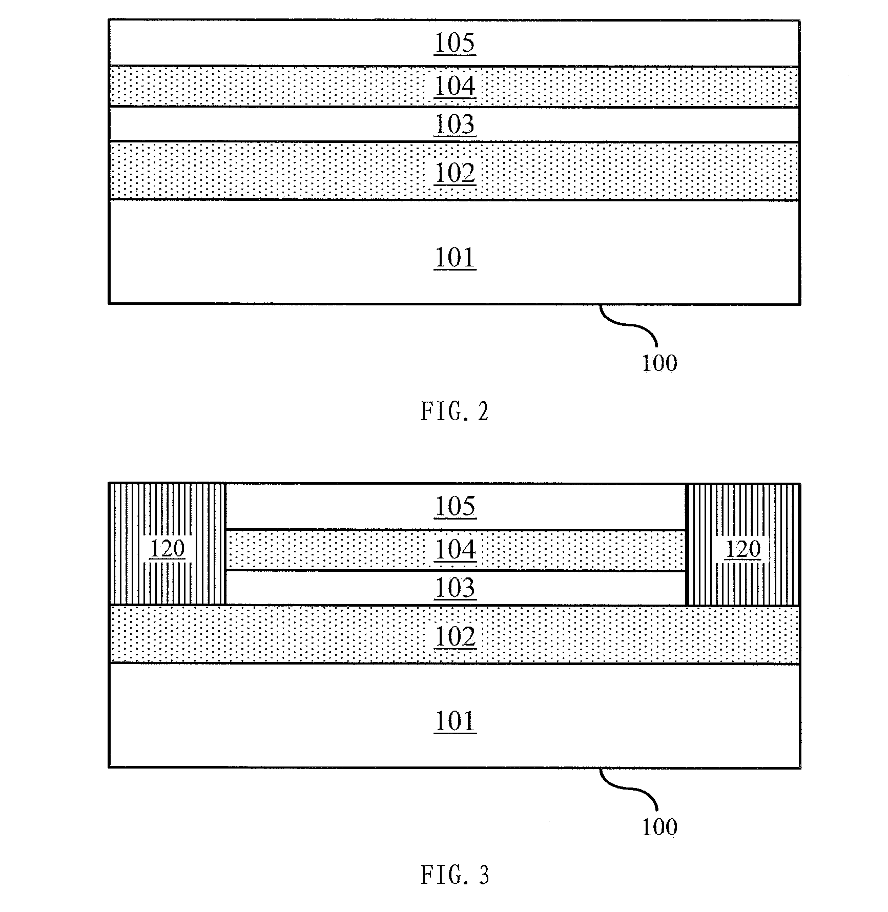
The present invention provides a method for manufacturing a semiconductor structure, which comprises following steps: providing a substrate, which comprises upwards in order a base layer, a buried isolation layer, a buried ground layer, an ultra-thin insulating buried layer and a surface active layer; implementing ion implantation doping to the buried ground layer; forming a gate stack, sidewall spacers and source / drain regions on the substrate; forming a mask layer on the substrate that covers the gate stack and the source / drain regions, and etching the mask layer to expose the source region; etching the source region and the ultra-thin insulating buried layer under the source region to form an opening that exposes the buried ground layer; filling the opening through epitaxial process to form a contact plug for the buried ground layer. Accordingly, the present invention further provides a semiconductor structure. The present invention proposes formation of a buried ground layer contact plug, which thence connects buried ground layer electrically to source region, thereby enhancing control capabilities of a semiconductor device over threshold voltages, suppressing short-channel effects and improving device performance; whereas no independent contact is required to build for the buried ground layer, which thence saves device area and simplifies manufacturing process accordingly.

Description

[0001]The present application claims priority benefit of Chinese patent application No. 201210134597.X, filed on 28 Apr. 2012, entitled “SEMICONDUCTOR STRUCTURE AND METHOD FOR MANUFACTURING THE SAME”, which is herein incorporated by reference in its entirety.FIELD OF THE INVENTION[0002]The present invention relates to semiconductor manufacturing field, particularly, to a semiconductor structure and a method for manufacturing the same.BACKGROUND OF THE INVENTION[0003]In order to improve both performance and integrity of integrated circuit chips, feature sizes of devices are scaled down continually in view of Moore's law, which nowadays have already reached into the nanometer regime. Traditional planar bulky Si CMOS technology cannot any more boost improvement in device performance and decrease power consumption at the meantime of improving integrity of circuits. Consequently, device parameters fluctuate randomly and the threshold voltage cannot be scaled down proportionally, which fu...

Claims


Application Information

Patent Timeline
IPC IPC(8): H01L27/12H01L29/66H01L21/266H01L21/02H01L21/306H01L21/308H01L21/768H01L29/78H01L21/84
CPCH01L27/1203H01L29/78H01L29/66659H01L21/266H01L21/02529H01L21/30604H01L21/3081H01L21/76897H01L21/02532H01L21/84H01L29/66772H01L29/78612H01L29/78648H01L21/743H01L21/2652H01L29/165H01L29/66636
Inventor YIN, HAIZHOUZHU, HUILONGLUO, ZHIJIONG
Owner INST OF MICROELECTRONICS CHINESE ACAD OF SCI
Learn More