
Nonvolatile memory cell and fabrication method thereof

a non-volatile memory cell, fabrication method technology, applied in the direction of semiconductor devices, electrical apparatus, transistors, etc., can solve the problem of insufficient erase efficiency of prior art non-volatile memory cell structures, and achieve the effect of increasing erase efficiency

Active Publication Date: 2018-12-20
UNITED MICROELECTRONICS CORP
View PDF4 Cites 8 Cited by
  • Summary
  • Abstract
  • Description
  • Claims
  • Application Information

AI Technical Summary

Benefits of technology

The patent is about a memory cell that can be erased more easily than previous designs. The technical effect is that this cell is more efficient in its erasing process.

Problems solved by technology

In general, the prior art nonvolatile memory cell structures have insufficient erase efficiency.

Method used


Image

  • Nonvolatile memory cell and fabrication method thereof
  • Nonvolatile memory cell and fabrication method thereof
  • Nonvolatile memory cell and fabrication method thereof

Examples


Embodiment Construction

[0011]The present invention has been particularly shown and described with respect to certain embodiments and specific features thereof. The embodiments set forth herein below are to be taken as illustrative rather than limiting. It should be readily apparent to those of ordinary skill in the art that various changes and modifications in form and detail may be made without departing from the spirit and scope of the invention.

[0012]Before the further description of the preferred embodiment, the specific terms used throughout the text will be described below.

[0013]The term “etch” is used herein to describe the process of patterning a material layer so that at least a portion of the material layer after etching is retained. For example, it is to be understood that the method of etching silicon involves patterning a mask layer (e.g., photoresist or hard mask) over silicon and then removing silicon from the area that is not protected by the mask layer. Thus, during the etching process, t...


PUM


Abstract

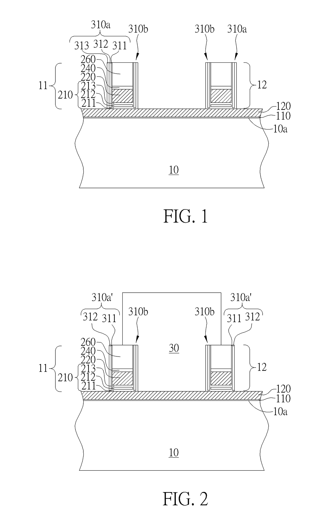
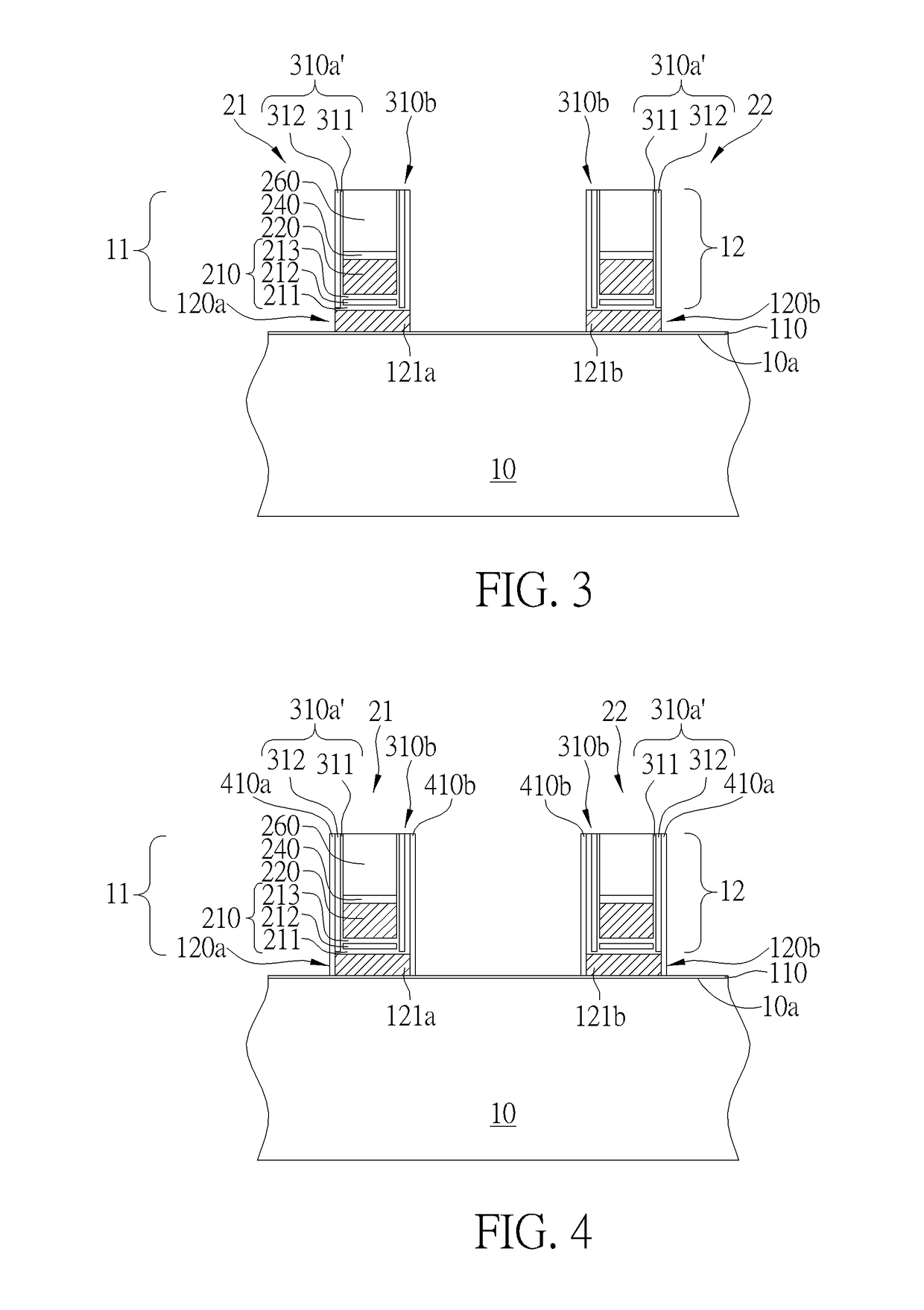
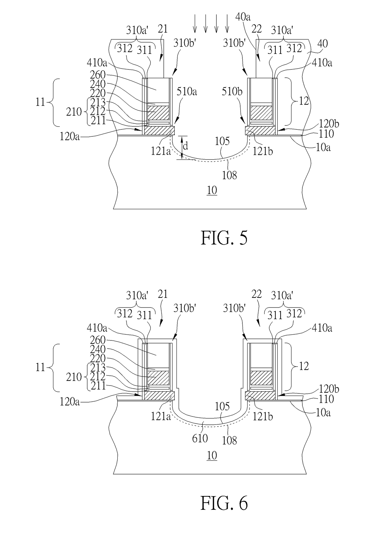
A nonvolatile memory cell includes a substrate having a drain region, a source region, and a channel region between the drain region and the source region. A floating gate and a select gate are disposed on the channel region. A control gate is disposed on the floating gate. An erase gate is disposed on the source region. The erase gate includes a lower end portion that extends into a major surface of the substrate.

Description

BACKGROUND OF THE INVENTION1. Field of the Invention[0001]The present invention relates generally to the field of semiconductor memory devices. More particularly, the present invention relates to a nonvolatile memory cell and a method for fabricating the same.2. Description of the Prior Art[0002]Nonvolatile memory cells are known in the art. For example, U.S. Pat. No. 9,548,312 discloses a type of nonvolatile memory cell structure including a floating gate and a select gate over a channel region of a substrate. The floating gate is insulated from the select gate. The select gate is disposed over a first end portion of the floating gate and covers a first sidewall of the floating gate.[0003]An erase gate, which is disposed on a source region and is spaced apart from the select gate, is formed over a second end portion of the floating gate and covers a second sidewall of the floating gate that is opposite to the first sidewall. The erase gate is insulating from the floating gate by a ...

Claims


Application Information

Patent Timeline
Patent Type & Authority Applications(United States)
IPC IPC(8): H01L27/11521H01L27/11556H10B41/30H10B41/27
CPCH01L27/11521H01L27/11556H01L29/42328H01L29/788H01L29/66825H01L29/42336H01L29/40114H10B41/35
Inventor YI, LIANGCHANG, CHIH-CHIENWANG, SHEN-DE
Owner UNITED MICROELECTRONICS CORP
Learn More