
Wireless Microphone and/or In-Ear Monitoring System and Method of Controlling a Wireless Microphone and/or In-Ear Monitoring System

a monitoring system and wireless microphone technology, applied in multi-frequency code systems, digital transmission, mouthpiece/microphone attachments, etc., can solve the problem of inability to exchange control information in a directional manner, and achieve the effect of minimizing time elapse and effective utilization of time slots

Active Publication Date: 2018-12-20
SENNHEISER ELECTRONICS GMBH & CO KG
View PDF6 Cites 1 Cited by
  • Summary
  • Abstract
  • Description
  • Claims
  • Application Information

AI Technical Summary

Benefits of technology

The invention allows multiple devices to communicate without interference by sharing information about their goals simultaneously. This helps ensure efficient use of space during communication while reducing delays between detecting and transmitting samples.

Problems solved by technology

The technical problem addressed in this patent text needs to be identified by a senior R&D personnel.

Method used


Image

  • Wireless Microphone and/or In-Ear Monitoring System and Method of Controlling a Wireless Microphone and/or In-Ear Monitoring System
  • Wireless Microphone and/or In-Ear Monitoring System and Method of Controlling a Wireless Microphone and/or In-Ear Monitoring System

Examples


Embodiment Construction

[0031]It is to be understood that the figures and descriptions of the present invention have been simplified to illustrate elements that are relevant for a clear understanding of the present invention, while eliminating, for purposes of clarity, many other elements which are conventional in this art. Those of ordinary skill in the art will recognize that other elements are desirable for implementing the present invention. However, because such elements are well known in the art, and because they do not facilitate a better understanding of the present invention, a discussion of such elements is not provided herein.

[0032]The present invention will now be described in detail on the basis of exemplary embodiments.

[0033]The wireless microphone and / or in-ear monitoring system according to the invention represents a so-called program making special event system PMSE.

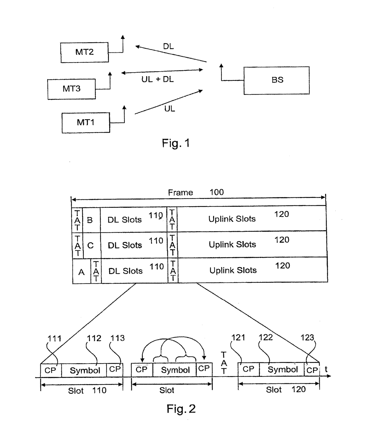
[0034]FIG. 1 shows a diagrammatic view of wireless microphone and / or in-ear monitoring system according to a first embodiment...


PUM


Abstract

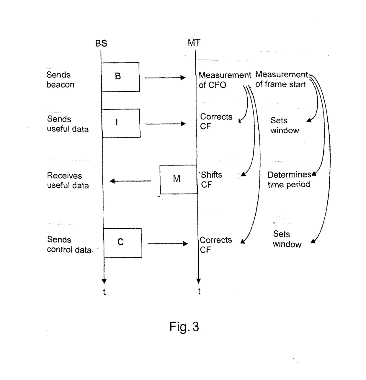
A wireless microphone and/or in-ear monitoring system having at least one first mobile device for wirelessly transmitting first audio signals. The system also has at least one base station for wirelessly receiving the first audio signals transmitted by the mobile device. The wireless transmission is based on an orthogonal frequency-division multiplexing transmission (OFDM) during a time-division multiple access (TDMA) time slot. Each wireless microphone occupies at least one slot within 2 ms. Each of the TDMA frames has a plurality of slots which respectively have precisely one OFDM symbol. Accordingly, precisely one OFDM symbol is transmitted in each TDMA slot. During a time slot made available in accordance with the TDMA, a transmission is effected on the basis of an OFDM method. The TDMA frame length is so short as a latency of <4 ms is required for professional audio transmission, for example in the case of wireless microphone systems.

Description


Claims


Application Information

Patent Timeline
Owner SENNHEISER ELECTRONICS GMBH & CO KG
Learn More