Mobile communications network, communications device and methods

a technology of communication device and communication network, applied in the direction of machine-to-machine/machine-type communication service, transmission path division, wireless communication, etc., can solve the problems of reducing capability, requiring more complex and expensive radio transceivers to implement, and presenting disadvantages and challenges to successful deployment, etc., to achieve the effect of reducing capability

Active Publication Date: 2018-12-20
SONY GRP CORP
View PDF1 Cites 1 Cited by
  • Summary
  • Abstract
  • Description
  • Claims
  • Application Information

AI Technical Summary

Benefits of technology

This solution enables efficient use of communications resources, allowing both types of reduced capability devices to operate within the same network without interoperability issues, optimizing bandwidth and reducing the complexity and cost of radio transceivers for MTC-type devices.

Problems solved by technology

Whilst it can be convenient for a terminal such as an MTC type terminal to take advantage of the wide coverage area provided by a third or fourth generation mobile telecommunication network, there are at present disadvantages and challenges to successful deployment.
Furthermore, while the type of functions performed by the MTC-type terminal (e.g. collecting and reporting back data) do not require particularly complex processing to perform, third and fourth generation mobile telecommunication networks typically employ advanced data modulation techniques (such as 16 QAM or 64 QAM) on the radio interface which can require more complex and expensive radio transceivers to implement.
However, there may different types of reduced capability devices and as a result a deployment of a mobile communications network which is configured to support one type of reduced capability device may not be compatible with another form of reduced capability device.

Method used


Image

  • Mobile communications network, communications device and methods
  • Mobile communications network, communications device and methods
  • Mobile communications network, communications device and methods

Examples


Embodiment Construction

Example of an LTE System

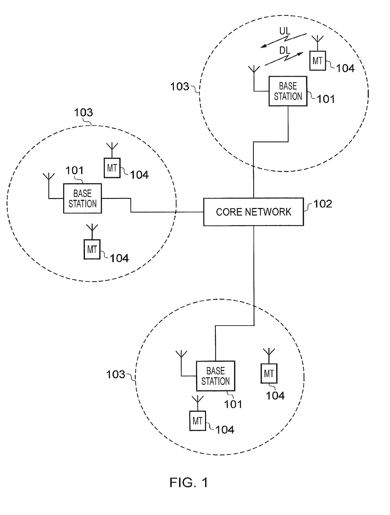
[0028]FIG. 1 provides a schematic diagram illustrating some basic functionality of a conventional mobile telecommunications network, using for example a 3GPP defined UMTS and / or Long Term Evolution (LTE) architecture.

[0029]The network includes a plurality of base stations 101 connected to a core network 102. Each base station provides a coverage area 103 (i.e. a cell) within which data can be communicated to and from communications devices (also referred to as mobile terminals, MT or User equipment, UE) 104. Data is transmitted from base stations 101 to communications devices 104 within their respective coverage areas 103 via a radio downlink Data is transmitted from communications devices 104 to the base stations 101 via a radio uplink. The core network 102 routes data to and from the communications devices 104 via the respective base stations 101 and provides functions such as authentication, mobility management, charging and so on.

[0030]Mobile telecommunic...


PUM


Abstract

A communications device is configured to receive data from a wireless access interface transmitted by a mobile communications network. The wireless access interface provides a plurality of communications resource elements within a system bandwidth providing a host frequency range of a host carrier and reserved communications resources for preferable allocation to reduced capability devices, the reserved communications resources forming a virtual carrier. In each of a plurality of time divided units, the wireless access interface provides a shared channel of communications resources and a control channel formed within the communications resources of the system bandwidth of the host frequency range for communicating resource allocation messages to communications devices. The resource allocation messages allocate the communications resources of the shared channel to the communication devices within the system bandwidth and allocate the reserved communications resources to the reduced capability devices.

Description

CROSS-REFERENCE TO RELATED APPLICATIONS[0001]This application is a continuation of U.S. Ser. No. 15 / 112,120, filed Jul. 15, 2016, which is a national stage (under 35 U.S.C. 371) of International Patent Application No. PCT / EP2014 / 078087, filed Dec. 16, 2014, claiming priority to European Patent Application No. 14152355.5, filed Jan. 23, 2014, both of which are herein incorporated by reference in their entirety.TECHNICAL FIELD OF THE DISCLOSURE[0002]The present disclosure relates to mobile communications networks and methods for communicating data using mobile communications networks, infrastructure equipment for mobile communications networks, communications devices for receiving data via mobile communications networks and methods of communicating via mobile communications networks.BACKGROUND OF THE DISCLOSURE[0003]Third and fourth generation mobile telecommunication systems, such as those based on the 3GPP defined UMTS and Long Term Evolution (LTE) architecture are able to support m...

Claims


Application Information

Patent Timeline
Patent Type & AuthorityApplications(United States)
IPC IPC(8): H04W72/12H04L5/00H04W72/04H04L27/26H04W4/70
CPCH04W72/1273H04L5/003H04W72/048H04L27/2601H04W4/70H04L5/001H04L5/0007H04L5/0037H04L5/0044H04L5/0053H04W72/51
InventorMARTIN, BRIAN ALEXANDERWEBB, MATTHEW WILLIAM
OwnerSONY GRP CORP