Wind directional system for arrangement between two vehicle parts of a rail vehicle

Active Publication Date: 2018-12-27
HUBNER GMBH
View PDF0 Cites 2 Cited by
  • Summary
  • Abstract
  • Description
  • Claims
  • Application Information

AI Technical Summary

Benefits of technology

The invention aims to improve a fairing used between two vehicle parts of a rail vehicle. It reduces the movement of the fairing elements and prevents displacement at the front faces of the vehicle parts. It also aims to minimize friction between the fairing elements and prevents gap formation while extending the life of the fairing elements.

Problems solved by technology

If the fairing were to be configured from a single-part peripheral fairing element, this fairing element would suffer from a high mass, would be difficult to manufacture and difficult to install, and would consequently also only be able to be replaced as a whole.
A deformation movement in the lateral direction in particular takes place in addition to the sliding movement over the contact surfaces of the oppositely disposed fairing elements on movements in the transverse displacement direction between the vehicle parts so that shoulders can disadvantageously result in the region of the transition between two fairing elements at a common vehicle part due to displacement movements.

Method used


Image

  • Wind directional system for arrangement between two vehicle parts of a rail vehicle
  • Wind directional system for arrangement between two vehicle parts of a rail vehicle
  • Wind directional system for arrangement between two vehicle parts of a rail vehicle

Examples


Embodiment Construction

[0031]The present invention provides various embodiments of fairing. Such fairings may take a variety of forms. Certain examples of the present invention are shown in the figures. However, the present invention is not limited to the illustrated embodiments. Additional advantages, objects, and features of the invention will be set forth in part in the description that follows and in part will become apparent to those having ordinary skill in the art upon examination of the following or may be learned from practice of the invention.

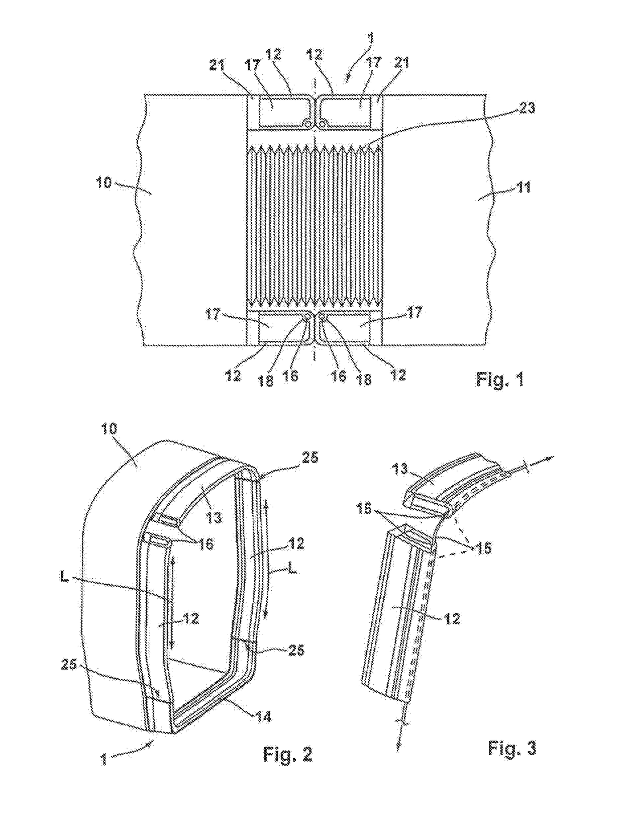
[0032]FIG. 1 shows a schematized view of the arrangement of a fairing 1 between a first vehicle part 10 and a second vehicle part 11. The fairing 1 is part of a transition between the two vehicle parts 10, 11 and is arranged substantially aligned with the outer side of the vehicle parts 10, 11. An inner bellows 23 is located within the fairing 1 between the vehicle parts 10, 11. Together with further components, not shown, in particular a base assembly, the...


PUM


Abstract

A fairing for arrangement between two vehicle parts, in particular of a rail vehicle, movably connected to one another, having at least one fairing element that is arranged at a respective vehicle part, that is elastically deformable, and that has a U-shaped or arcuate cross-section. The fairing also has at least one stabilization body that extends at least sectionally into the fairing element and extends from at least one front face of the fairing element.

Description

CROSS-REFERENCE TO RELATED APPLICATIONS[0001]This application claims priority of German Patent Application 10 2017 113 761.0 filed Jun. 21, 2017.FIELD OF THE INVENTION[0002]The present invention relates to a wind directional device for arrangement between two vehicle parts, in particular of a rail vehicle, that are movably connected to one another, comprising at least one wind directional element that is arranged at a respective vehicle part, that is elastically deformable, and that has a U-shaped or arcuate cross-section. The invention is furthermore directed to a wind directional element for forming a wind directional device composed of at least one such wind directional element. Such wind directional devices are also known in technical terminology by the term “fairings” that will be used in the present application.BACKGROUND OF THE INVENTION[0003]DE 20 2010 001 793 U1, for example, discloses a fairing forming the category that is configured for arrangement between two vehicles pa...

Claims


Application Information

Patent Timeline
IPC IPC(8): B61D17/22
CPCB61D17/22B61D17/02B61D17/20B62D35/00
Inventor KRUG, LARSWIEGREFE, ANDREAS
Owner HUBNER GMBH
Why Eureka
Try Eureka