
Sensor based door closer with an intelligent control system

a door closer and sensor technology, applied in the field of automatic door closing devices, can solve the problems of increased probability of accidents in high-traffic hallways or stairwells, hit persons on the opposite side of the door, and possible harm, so as to reduce liability risks, reduce damage to the door system, and save heating costs

Active Publication Date: 2018-12-27
LADHA RIAZ +1
View PDF0 Cites 4 Cited by
  • Summary
  • Abstract
  • Description
  • Claims
  • Application Information

AI Technical Summary

Benefits of technology

The present invention aims to reduce the number of injuries associated with a quick opening of a door. It does this by utilizing the fact that springs can dampen motion and that this dampening force increases as the springs' extension increases. This design also allows a cushioned stopping force for anyone who may be approaching the door in high speed. Additionally, the design is an add-on upgrade to existing door closers, which reduces the hurdle of replacing or revamping the existing door closers. Its objectives include preventing potential damage to all entities within close proximity to the door, being easy to maintain and can be mounted on any door closer, having a softer dampening effect, avoiding abrupt stoppages to motion, and reducing liability risks by reducing of damage to door systems and possibly save on heating costs.

Problems solved by technology

When people are in the process of entering or exiting a door, they may swing the door, which may hit persons on the opposite side of the door.
In such situations, for example, person-A exiting may be in a tight quarter, and person-B entering may be in a hurry, pushing the door into person-A, causing possible harm.
The probability of this accident increases in high traffic hallways or stairwells.
All of these accidents happened because people did not know if there is another person on the other side of the door.

Method used


Image

  • Sensor based door closer with an intelligent control system
  • Sensor based door closer with an intelligent control system
  • Sensor based door closer with an intelligent control system

Examples


Embodiment Construction

[0035]The device disclosed herein, in accordance with one or more various embodiments, is described in detail with reference to the following figures. The drawings are provided for purposes of illustration only and merely depict typical or example embodiments of the disclosed technology. These drawings are provided to facilitate the reader's understanding of the disclosed technology and shall not be considered limiting of the breadth, scope, or applicability thereof. It should be noted that for clarity and ease of illustration these drawings are not necessarily made to scale.

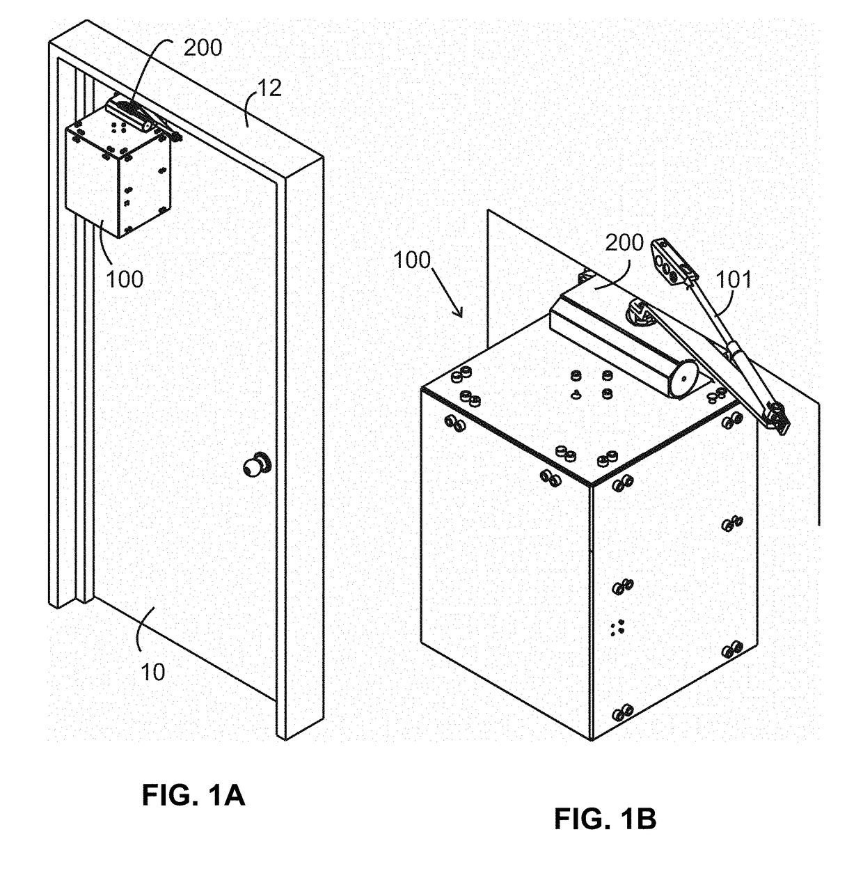
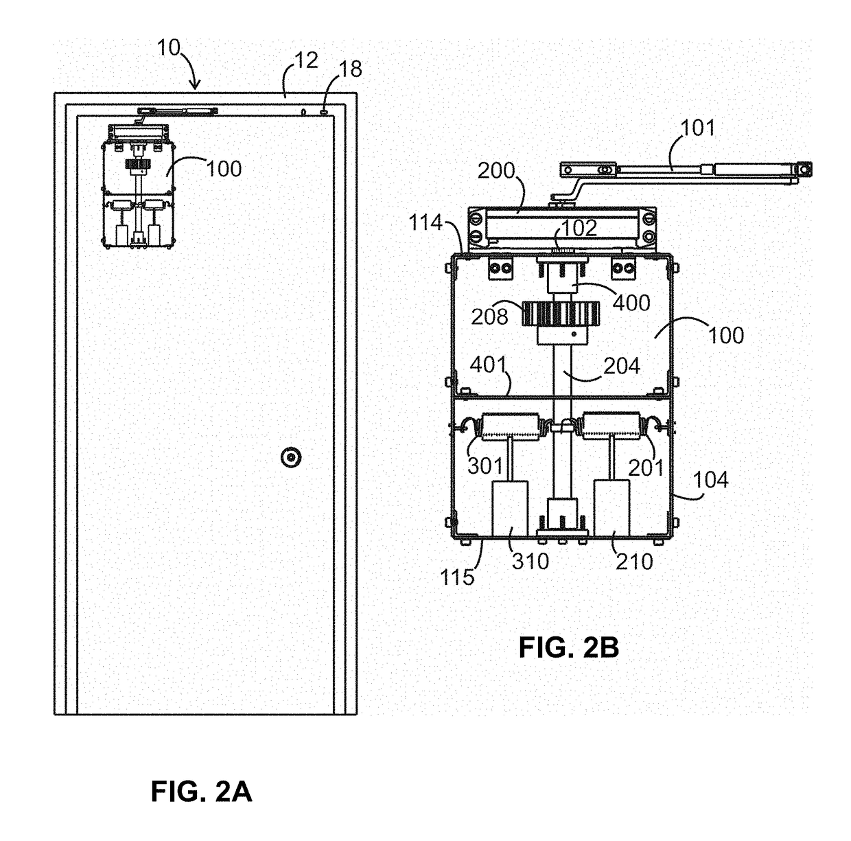
[0036]As shown in FIG. 1, the present invention is a control system 100 that can be added to an existing door closer 200 to prevent a rapid opening and closing of a door 10 by a person when another person may be on the other side of the door 10. A door closer 200 is typically found on the top of many doors and can be easily installed.

[0037]A typical door closer is designed to translate the push force by the user...


PUM


Abstract

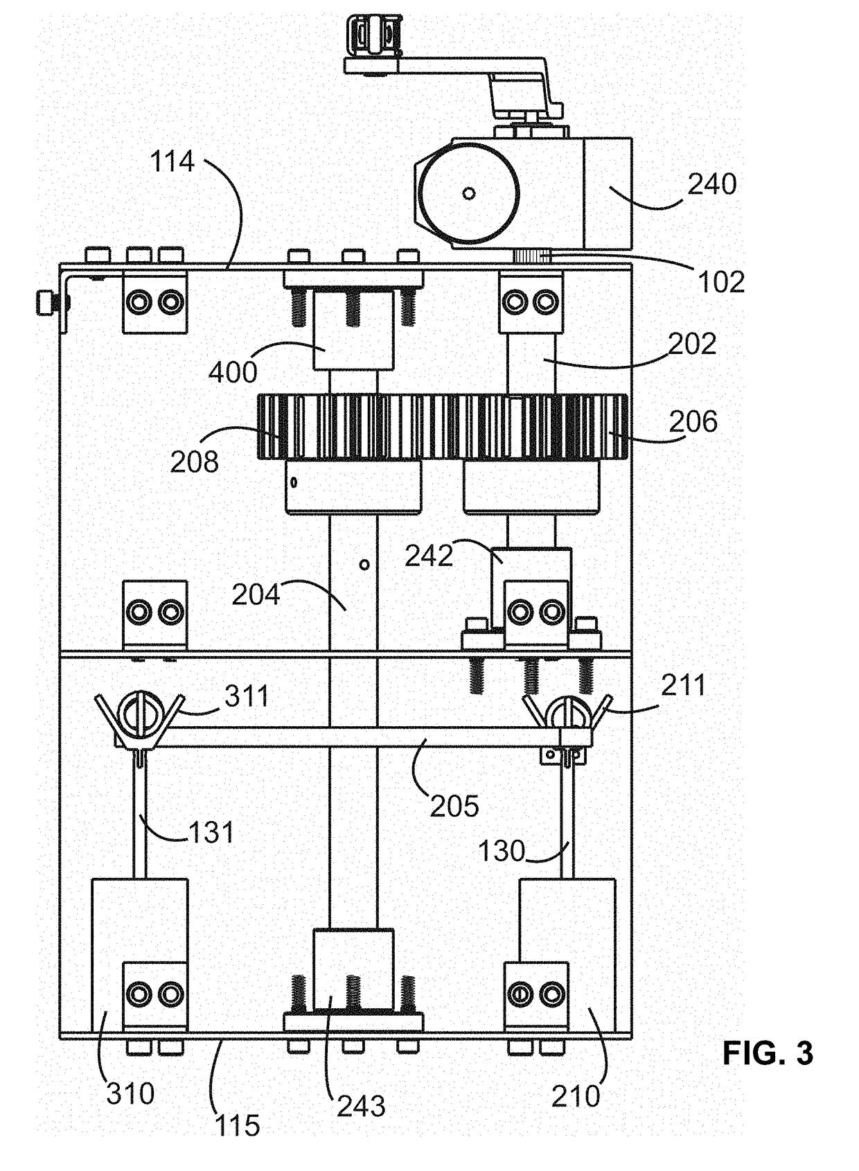
The present invention provides a door closer control system that includes a door closer having a rack and pinion mechanism connected to a pair of shafts with different length and a pair of springs. The shorter shaft is attached to the pinion of the door closer and will rotate in conjunction with the pinion as the door opens or closes. The shafts have correspondent gears connected to the shafts. The rotation of the first gear will be meshing with the second gear on the second shaft. Electronic sensors are placed on both sides of the door to detect a presence of an object and are activated by the movement of the solenoids. The movement of the solenoids cause a set of springs in the system to engage and disengage from a link to allow free motion of the door.

Description

FIELD OF THE INVENTION[0001]The present invention relates in general to the field of automatic door closing devices, and in particular to a door closer system for dampening the motion of a door.BACKGROUND OF THE INVENTION[0002]Door closers are used to automatically close doors; hold doors open for short intervals, and control opening / closing speeds of a door in order to facilitate passage through a doorway and to help ensure that doors are not inadvertently left open. A door closer is often attached to the top or the bottom of a door. When the door is opened and released, the door closer generates a mechanical force that causes the door to automatically close without any user input.[0003]When people are in the process of entering or exiting a door, they may swing the door, which may hit persons on the opposite side of the door. This is especially noticeable around restrooms where opaque doors are necessary. In such situations, for example, person-A exiting may be in a tight quarter,...

Claims


Application Information

Patent Timeline
IPC IPC(8): E05F15/42E05F15/73E05F3/10
CPCE05F15/42E05F3/102E05F15/73E05F3/22E05Y2201/21E05Y2201/462E05Y2400/302E05Y2400/53E05Y2400/532E05Y2900/132E05F15/40
Inventor LADHA, RIAZLADHA, FAISAL
Owner LADHA RIAZ
Learn More