Connection structure for storage shelf

a technology for connecting structures and storage shelves, applied in the direction of cabinets, dismountable cabinets, fastening means, etc., can solve the problems of poor appearance, influence on welding quality, and welding traces between the fixing frame and the four fitting sleeves, so as to avoid the use of welding flux and ensure the connection. stability, avoiding the effect of welding flux cos

Inactive Publication Date: 2018-12-27
WIRE MASTER IND
View PDF6 Cites 3 Cited by
  • Summary
  • Abstract
  • Description
  • Claims
  • Application Information

AI Technical Summary

Benefits of technology

[0012]In assembly, each fitting sleeve is fitted in each first groove of the first peripheral tab and each second groove of the second peripheral tab, and the plural first vertical ribs and the plural second vertical ribs contact with the multiple first bosses and the multiple second bosses respectively so that the multiple first bosses and the multiple second bosses are connected with the plural first vertical ribs and the plural second vertical ribs individually in a high frequency welding manner, thus connecting each fixing frame and each fitting sleeve together securely.
[0013]Preferably, each fitting sleeve is fitted in each first groove and each second groove of each fixing frame of each support plate so as to be covered by each fixing frame in the high frequency welding manner, thus obtaining stable connection, avoiding using cost of welding flux, accelerating production time, and achieving aesthetic appearance. Preferably, each fitting sleeve is connected with each fixing frame securely.

Problems solved by technology

However, welding traces occur among the fixing frame and the four fitting sleeves to have poor appearance and to influence welding quality.

Method used


Image

  • Connection structure for storage shelf
  • Connection structure for storage shelf
  • Connection structure for storage shelf

Examples


Embodiment Construction

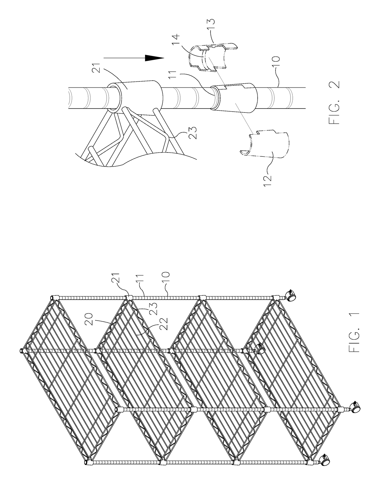
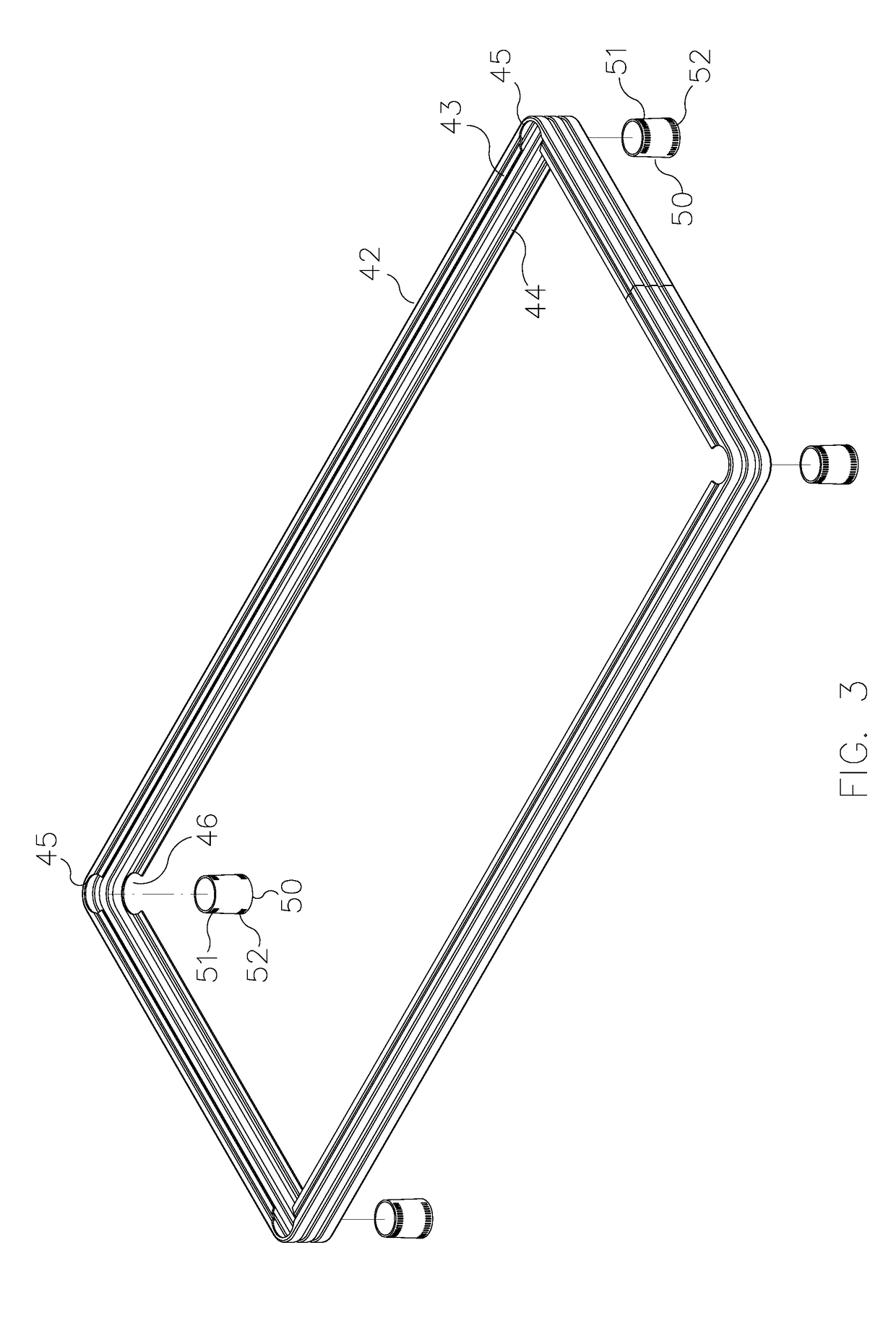
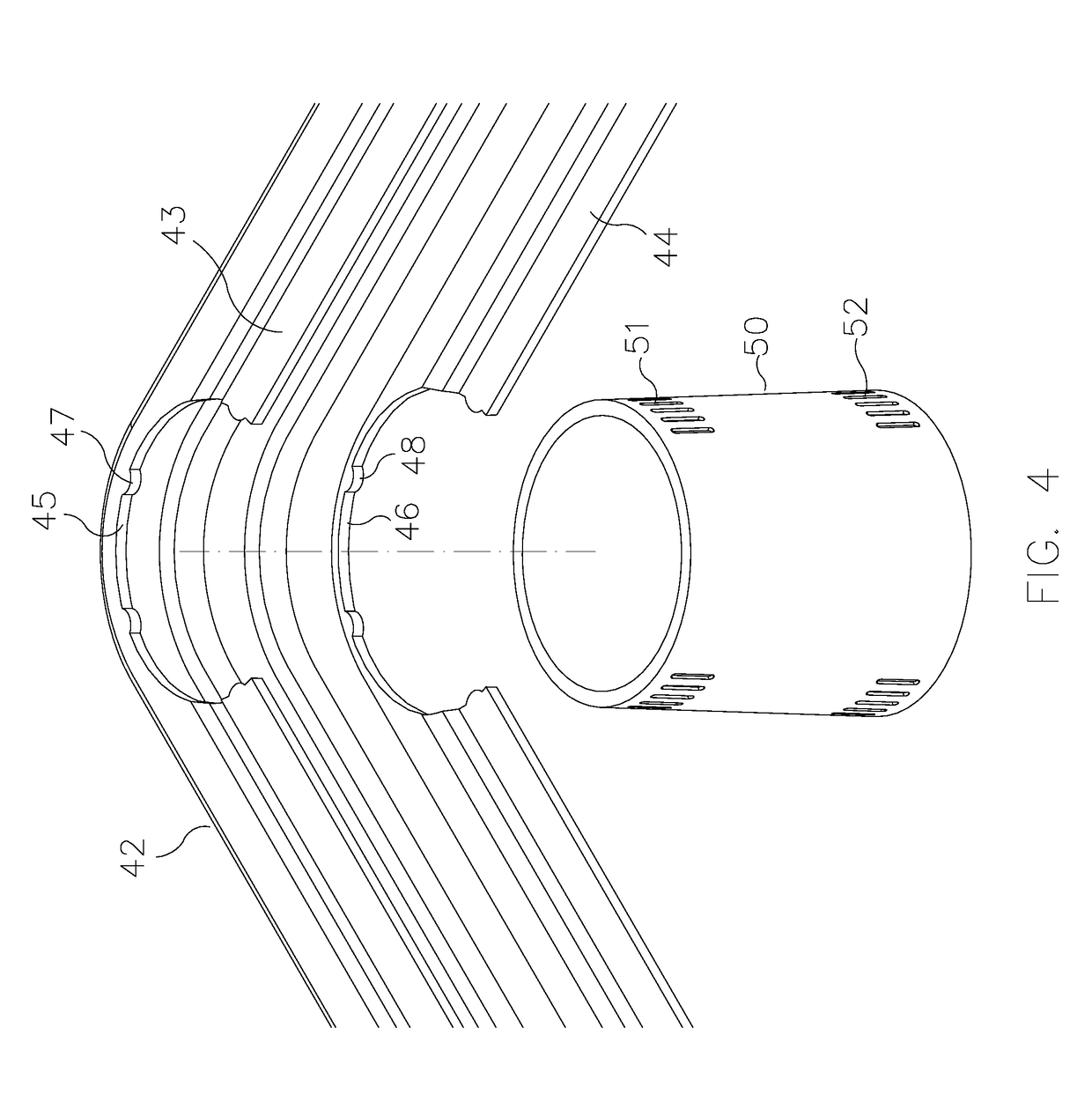
[0027]With reference to FIGS. 3 to 13, a connection structure for a storage shelf according to a preferred embodiment of the present invention comprises: multiple metal sheets 41 and multiple fixing frames 42 which are connected together so as to form a plurality of support plates 40 of the storage shelf 30, wherein each of the multiple fixing frames 42 has four fitting sleeves 50 arranged on four corners of each fixing frame 42 respectively and fitted with four posts 32 of the storage shelf 30 individually by way of four plastic fitting elements 32, thus assembling the storage shelf 30.

[0028]As connecting each of the plurality of support plates 40 with each of the four fitting sleeves 50, a first peripheral tab 43 and a second peripheral tab 44 extend inwardly from an inner wall of each fixing frame 42, wherein the first peripheral tab 43 is located above the second peripheral tab 44 and is connected with each of the multiple metal sheets 41, and the second peripheral tab 44 suppor...


PUM

PropertyMeasurementUnit
frequencyaaaaaaaaaa
perimeteraaaaaaaaaa
plasticaaaaaaaaaa

Abstract

A connection structure for a storage shelf, the storage shelf contains four posts fitting with plural support plates respectively by using multiple plastic fitting elements, and each support plate includes a metal sheet and a fixing frame. The fixing frame has four fitting sleeves fitted with the four posts individually by using the multiple plastic fitting elements. A first peripheral tab and a second peripheral tab extend inwardly from an inner wall of the fixing frame, and the first peripheral tab is located above the second peripheral tab. The fixing frame has four first grooves, and the fixing frame also has four second grooves. Each fitting sleeve has plural first vertical ribs surrounding an outer wall thereof and corresponding to the first peripheral tab, and each fitting sleeve has plural second vertical ribs surrounding the outer wall of each fitting sleeve and corresponding to the second peripheral tab.

Description

FIELD OF THE INVENTION[0001]The present invention relates to a connection structure for a storage shelf in which each fixing frame and each fitting sleeve are securely connected together.BACKGROUND OF THE INVENTION[0002]With reference to FIGS. 1 and 2, a conventional storage shelf contains at least four posts 10, and between any two adjacent of the at least four posts 10 are defined multiple recesses 11 so as to fit with two plastic fitting elements 12, 13. Each of the two plastic fitting elements 12, 13 has a rib 14 retaining with each of the multiple recesses 11. Each of the two plastic fitting elements 12, 13 is conical, and four fitting sleeves 21 are arranged on four corners of each of plural support plates 20 respectively, wherein each of the four fitting sleeves 21 is conical so as to mate with the two plastic fitting elements 12, 13, thus connecting each support plate 20 and the at least four posts 10 together. In addition, each support plate 20 has multiple metal bars welde...

Claims


Application Information

Patent Timeline
Patent Type & Authority Applications(United States)
IPC IPC(8): F16B12/02A47B47/00A47B96/02
CPCA47B57/34A47B57/545A47B47/0083A47B96/024F16B12/02
Inventor CHENG, HSI-MING
Owner WIRE MASTER IND
Why Eureka
Try Eureka