
Electronic apparatus

a technology of electronic equipment and antenna unit, applied in the direction of antenna details, antenna earthings, antennas, etc., can solve the problems of increasing the size of the electronic apparatus as a whole, deteriorating the reception and affecting the overall performance of the electronic apparatus, so as to achieve compact electronic apparatus and good receiving characteristics of the antenna uni

Active Publication Date: 2018-12-27
LENOVO PC INT
View PDF1 Cites 11 Cited by
  • Summary
  • Abstract
  • Description
  • Claims
  • Application Information

AI Technical Summary

Benefits of technology

The present invention aims to provide an electronic apparatus with an antenna unit that is compact and has good receiving characteristics. A conductive thin film is used to define a shield wall for the antenna space, which prevents electromagnetic noise from affecting the antenna. This results in a smaller electronic apparatus that is still functional and efficient.

Problems solved by technology

In this case, the receiving characteristics of the antenna unit may deteriorate because the body chassis accommodates various types of electronic components, such as an arithmetic unit and a memory, which may be a noise source for the antenna unit.
Such a shielding wall, however, means an increase in size of the body chassis corresponding to the space required for the shielding wall, which makes the electronic apparatus as a whole larger.

Method used


Image

  • Electronic apparatus
  • Electronic apparatus
  • Electronic apparatus

Examples


Embodiment Construction

[0018]Referring to the drawings, the following describes an electronic apparatus according to the present invention in details by way of a preferable embodiment.

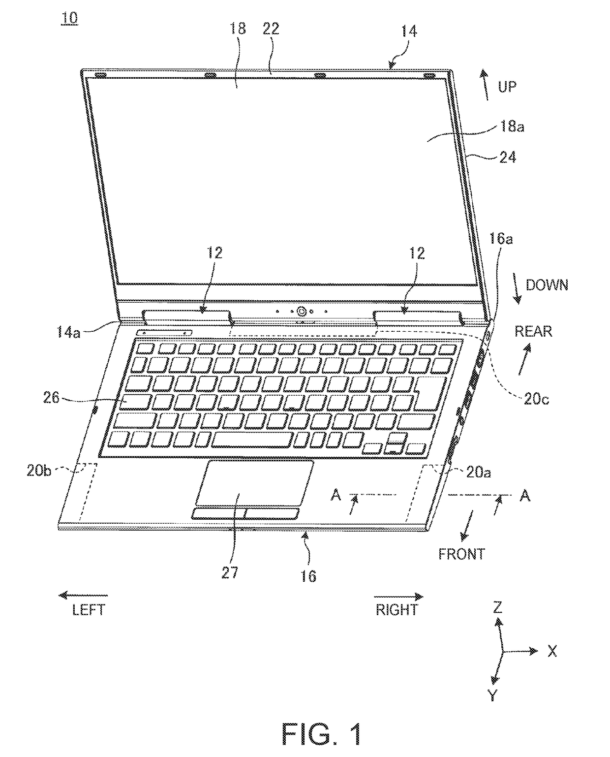
[0019]FIG. 1 is a perspective view of an electronic apparatus 10 according to one embodiment of the present invention. FIG. 1 shows the electronic apparatus 10 as a laptop PC during use, in which a display chassis 14 is opened relative to a body chassis 16 via hinge units 12.

[0020]The electronic apparatus 10 of the present embodiment is a so-called convertible type PC that can be openable from the 0-degree position to the 360-degree position. At the 0-degree position, the display chassis 14 is closed to the body chassis 16, and at the 360-degree position, the display chassis is flipped. That is, the electronic apparatus 10 can be preferably used as a laptop PC when the display chassis 14 is at an angle of about 90 degrees relative to the body chassis 16 (see FIG. 1). When the display chassis 14 rotates at an angle of 360 deg...


PUM


Abstract

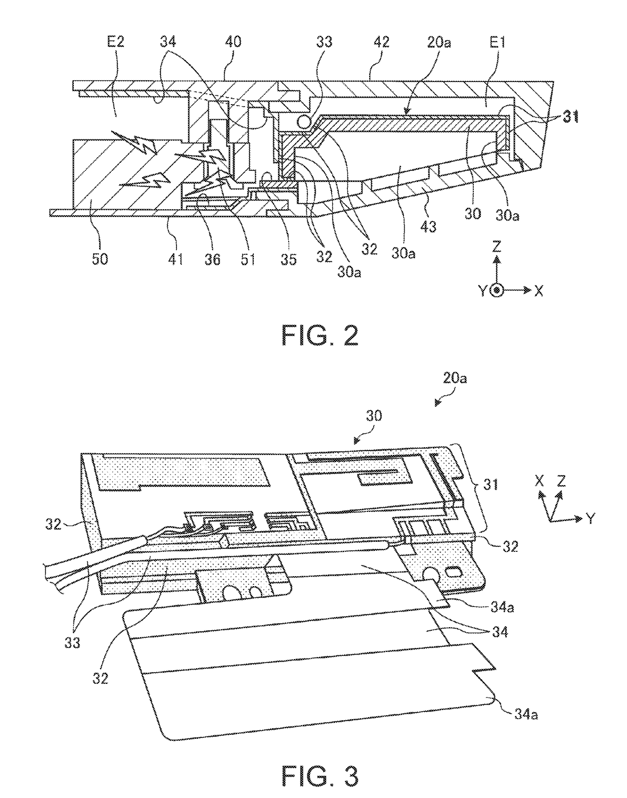
The present disclosure provides an electronic apparatus having an antenna unit at a body chassis. The electronic apparatus includes: a body chassis; an antenna supporting member disposed in an antenna space at a periphery of the body chassis, and having an upper face on which an antenna pattern is formed, the antenna space being surrounded with a dielectric cover; a shield wall for the antenna space, including a conductive thin film covering an entire lateral face of the antenna supporting member close to a center of the body chassis, an upper antenna ground element connected to the conductive thin film and the rear face of a keyboard cover member, and a lower antenna ground element connected to the conductive thin film and the rear face of a bottom-face cover member. The conductive thin film, the upper antenna ground element and the lower antenna ground element define the shield wall.

Description

FIELD OF THE INVENTION[0001]The present invention relates to an electronic apparatus having an antenna unit at a body chassis, and the electronic apparatus can be compact and the antenna unit can keep good receiving characteristics.BACKGROUND OF THE INVENTION[0002]An electronic apparatus, such as a laptop personal computer (laptop PC), typically has various wireless communication functions as in wireless LAN (Local Area Network) or wireless WAN (Wide Area Network). An antenna unit for such wireless communication has to be disposed away from a conductor such as metal to have a certain space therebetween.[0003]In order to keep the communication quality of the antenna unit of a laptop PC, the laptop PC typically includes an antenna unit at an upper end of the display chassis so that the antenna unit can be located at the uppermost part of the PC during use (see Patent Document 1, for example).[0004][Patent Document 1] Japanese Patent Application Laid-Open No. 2013-162413SUMMARY OF THE ...

Claims


Application Information

Patent Timeline
Patent Type & Authority Applications(United States)
IPC IPC(8): H01Q1/22H01Q1/52
CPCH01Q1/2266H01Q1/526H01Q1/48H01Q9/0421H01Q21/28
Inventor HAWAKA, SHIGEKAZUYAMAMOTO, OSAMUOKADA, TAKAAKI
Owner LENOVO PC INT
Learn More