Method of telecommunication in a system with multi-spot geographical coverage, corresponding terrestrial station and relay device

a technology of terrestrial stations and relay devices, applied in the field of telecommunication in a system with multi-spot geographical coverage, can solve the problems of limiting the halving the theoretical capacity of the system, and tying the technology to the limit, so as to prevent any total loss of coverage

Inactive Publication Date: 2018-12-27
IRT ANTOINE DE SAINT EXUPERY
View PDF2 Cites 0 Cited by
  • Summary
  • Abstract
  • Description
  • Claims
  • Application Information

AI Technical Summary

Benefits of technology

[0032]Thus, this particular embodiment of the invention relies on a wholly novel and inventive approach in which a same ground station is made to transmit information that can generate intra-system interference because this information will be retransmitted by the relay device (of the satellite or aircraft type) with a same color and a same sub-color. This ground station can then, for this information, apply the intra-system interference cancellation algorithms without its being necessary to set up a communications link between this ground station and the other ground stations (this is the case of the first known architecture), or else between this ground station and a unique point (this is the case of the second known architecture). In other words, the proposed solution enables the implementing of the intra-system interference cancellation algorithms while preventing information transfers between ground stations through the terrestrial network.
[0036]While enabling the implementation of the intra-system interference cancellation algorithms, this second implementation makes it possible to surpass the above-mentioned limits of the first implementation. Indeed, if a ground station does not have the capacity to convey all the information of one of the N colors, then this color is divided into M sub-colors and this ground station is replaced by M ground stations each possessing the capacity to convey all the information of one of the M sub-colors.
[0037]Another advantage of this first implementation is that it prevents any total loss of coverage in the spots associated with a color divided into several sub-colors. Indeed, even in the event of unavailability of a ground station transmitting the information on one of the sub-colors of the divided color to the (satellite or aircraft type) relay device, the proposed solution enables partial coverage of this spot because it receives information from the other sub-colors of the divided color (transmitted by ground stations other than those that are unavailable).
[0047]In this particular case of the third implementation, a same service is offered on the totality of the terrestrial geographical coverage zone (i.e. all the spots). Thus, a total loss of coverage is prevented in all the spots. Indeed, in the event of unavailability of one of the ground stations, the proposed solutions enables a partial coverage of all the spots since they receive each of the pieces of information transmitted by the ground stations other than the one that is unavailable. Furthermore, the capacity of this service can gradually expand through the increase, as and when needed, of the number of ground stations in operation.

Problems solved by technology

These technologies are however tending to approach their limits because of technological limits related to making equipment and because of saturation of the frequency planes.
However, the trade-off would be the requirement of total control over free-space atmospheric propagation which to date is at a level of development that is as yet insufficient for optical frequencies.
But it is unfortunately imperfect and there is interference between spots of a same color (also called intra-system interference) that limits the capacity of the system.
This is a major issue in space telecommunications.
This solution has the drawback of halving the theoretical capacity of the system whenever the number of colors is doubled.
For the high-capacity systems (for example more with than a hundred spots), the two known architectures are inapplicable (or hardly applicable) in practice.
Indeed, this would lead to assumptions of information transfers that would be prohibitive (in terms of information throughput rate, synchronization etc.) among ground stations (the case of the first architecture) or between the unique point and the ground stations (in the case of the second architecture).

Method used


Image

  • Method of telecommunication in a system with multi-spot geographical coverage, corresponding terrestrial station and relay device
  • Method of telecommunication in a system with multi-spot geographical coverage, corresponding terrestrial station and relay device
  • Method of telecommunication in a system with multi-spot geographical coverage, corresponding terrestrial station and relay device

Examples


first embodiment

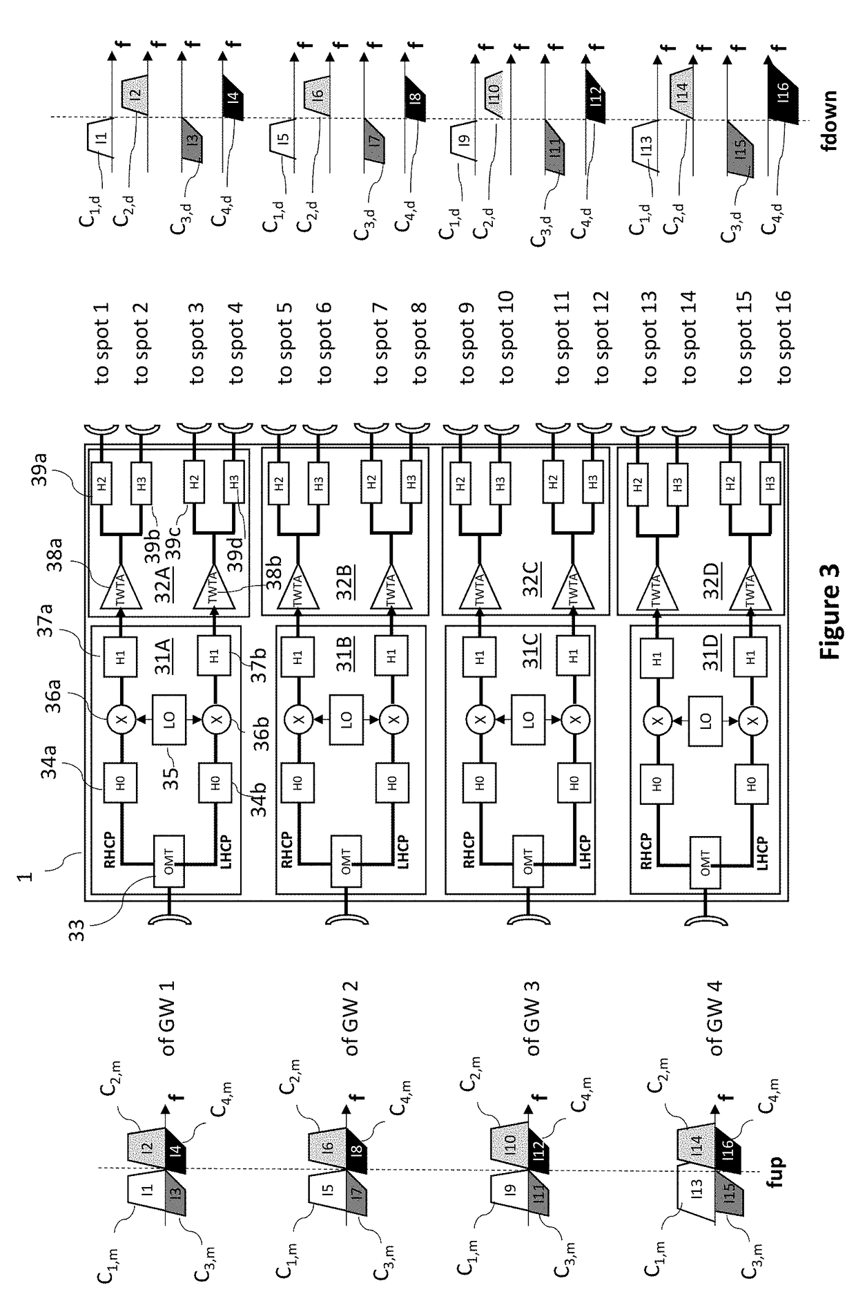
[0064]Referring now to FIG. 4, we present an example of a transmission of information from four ground stations GW1 to GW4 towards 16 spots (spot 1 to spot 16) via a satellite 1 in the invention (to be compared with the first solution like that of FIG. 3).

[0065]The ground station GW1 transmits information I1, I5, I9 and I13 to the satellite. This is information on the first colors C1,m, C2,m, C3,m and C4,m respectively (see definitions further above). The ground station GW2 transmits, to the satellite, the pieces of information I2, I6, I10 and I14 on the same first colors C1,m, C2,m, C3,m and C4,m respectively. The ground station GW3 transmits, to the satellite, the pieces of information I3, I7, I11 and I15 on the same first colors C1,m, C2,m, C3,m and C4,m respectively. The ground station GW4 transmits, to the satellite, the pieces of information I4, I8, I12 and I16 on the same first colors C1,m, C2,m, C3,m and C4,m respectively.

[0066]The satellite retransmits the pieces of informa...

second embodiment

[0078]Referring now to FIG. 5A, we present an example of transmission of information from 24 ground stations GW1 to GW24 to 144 spots (spot 1 to spot 144) via a satellite 1 according to the invention (to be compared with the second known solution of FIG. 6 discussed here below).

[0079]In this second embodiment, each of the four colors C1,d to C4,d is divided into six sub-colors (denoted sc1 to sc6). There are therefore 24 sub-colors in all. Each of the 24 ground stations is dedicated to a specific sub-color among these 24 sub-colors and transmits, to the satellite, all the information intended for transmission by the satellite with this specific sub-color. Thus, the interference cancelling algorithms (by subtraction at source) can be applied without any need for a network link between the ground stations.

[0080]For example, for the six colors sc1 to sc6 of the color C1,d:[0081]the ground station GW1 transmits, to the satellite, a first part of the pieces of information I1 to I36 inten...

third embodiment

[0099]Referring now to FIG. 7A, we present an example of transmission of information from 24 ground stations GW1 to GW24 towards 144 spots (spot 1 to spot 144) via a satellite 1 in the invention.

[0100]In this third embodiment, each of the four colors C1,d to C4,d is divided into 24 sub-colors (denoted sc1 to sc24). There are therefore 96 sub-colors in all. Each of the 24 ground stations is dedicated to an jth specific sub-color of each of the four colors, j∈{1 . . . 24}, and transmits, to the satellite, all the information to be transmitted by the satellite with the four jth specific sub-colors of the four colors.

[0101]For example, the ground station GW1 transmits the following to the satellite:[0102]a first part of the pieces of information I1 to I36 intended for retransmission by the satellite to the spots 1 to 36 respectively, with the sub-color sc1 of C1,d;[0103]a first part of the pieces of information I37 to I72, intended for retransmission by the satellite, to the spots 37 to...


PUM


Abstract

A method of telecommunications is proposed in a multi-spot geographical coverage system having an outbound path to transmit information, via a satellite or aircraft type relay device, from a plurality of ground stations to a plurality of terminals located in spots. Each downlink of the outbound path is associated with a color in an N-color re-use scheme with N≥2. For at least one color (or sub-color), one of the ground stations transmits to the relay device all the information intended for transmission by the relay device with this color or (sub-color).

Description

1. CROSS-REFERENCE TO RELATED APPLICATION[0001]This Application is a Section 371 National Stage Application of International Application No. PCT / EP2017 / 054968, filed Mar. 2, 2017, the content of which is incorporated herein by reference in its entirety, and published as WO 2017 / 149100 on Sep. 8, 2017, not in English.2. TECHNICAL FIELD[0002]The field of the invention is that of telecommunications via a satellite or aircraft type relay device. The term “aircraft” is understood to mean an airplane, a drone, a dirigible or a balloon. It is for example a high altitude platform (HAP) or high altitude platform station or high altitude pseudo-satellite (HAPS) also called a stratospheric platform.[0003]Such a satellite or aircraft type relay device possesses a reception antenna that receives signals sent out from ground stations or ground stations. In the relay device, these signals are filtered, transposed in frequency and amplified and then retransmitted (by transmission antennas) towards ...

Claims


Application Information

Patent Timeline
Patent Type & Authority Applications(United States)
IPC IPC(8): H04B7/185
CPCH04B7/18513H04B7/2041
Inventor MESNAGER, GILLESDECROIX, JACQUESSOMBRIN, JACQUES
Owner IRT ANTOINE DE SAINT EXUPERY
Why Eureka
Try Eureka