System and method for muscle movements detection

a detection system and muscle technology, applied in the field of muscle movement detection systems and methods, can solve the problems of affecting the ability to enhance the functionality of disabled persons affected by limb amputation, the inability of users to replicate touching senses, and the inability to conduct some complicated tasks,

Active Publication Date: 2019-01-03
MORADI ALI +7
View PDF7 Cites 2 Cited by
  • Summary
  • Abstract
  • Description
  • Claims
  • Application Information

AI Technical Summary

Benefits of technology

[0018]In an exemplary embodiment, one or more processors may be configured to detect at least one of the muscle contraction, the muscle relaxation, and the muscle inactivity based on the data captured at the first moment and the second moment by comparing the x-coordinate and y-coordinate as well as z-coordinate of each passive tag position of the first plurality of passive tags positions with the respective coordinates of the respective passive tag position of the second plurality of passive tags positions.
[0019]Furthermore, one or more processors may be configured to detect at least one of the muscle contraction, the muscle relaxation, and the muscle inactivity based on the data captured at the first moment and the second moment by comparing the y-coordinate of each passive tag position of the first plurality of passive tags positions with the y-coordinate of the respective passive tag position of the second plurality of passive tags positions and also by comparing the z-coordinate of each passive tag position of the first plurality of passive tags positions with the z-coordinate of the respective passive tag position of the second plurality of passive tags positions.
[0020]In an exemplary embodiment, one or more processors may be configured to detect the muscle contraction responsive to a value of the x-coordinate of the first associated tag position be smaller than a value of the x-coordinate of the second associated tag position, detect the muscle relaxation responsive to a value of the x-coordinate of the first associated tag position be larger than a value of the x-coordinate of the second associated tag position, and, detect the muscle inactivity responsive to a value of the x-coordinate of the first associated tag position be equal to a value of the x-coordinate of the second associated tag position.
[0021]According to one or more implementations of the present disclosure, a method may be performed by fixedly embedding a passive tag of a plurality of passive tags into a muscle of a plurality of muscles and capturing data associated with a first plurality of passive tags positions at a first moment by a plurality of on-board position readers attached to a wearable band. In an exemplary embodiment, the plurality of passive tags may be embedded in muscles of a plurality of muscles and a respective passive tag of the plurality of passive tags may be fixedly embedded into a respective muscle of the plurality of muscles in a configuration that responsive to the muscle being contracted or relaxed, the passive tag thereby moving.

Problems solved by technology

For example, limb amputation or nerve damage may substantially abort the movement intention.
Accordingly, their rehabilitation and ability to have enhanced functionality for disabled persons impacted by limb amputation is considered as a great issue.
If such rehabilitation tools are used, a user may not be able to replicate touching senses or conduct some complicated tasks such as writing, grasping, and manipulating a grasped object.
In addition, if an amputee is impacted by serious limb amputation or nerve cutting, wearing and controlling such an assist device may be substantially impossible.
However, since the planar type is generally utilized for studying a method for analyzing signals of a nerve system or a method for inputting information to the nerve system, it is not suitable to apply the planar type to a technique of connecting a nerve system and an artificial device.
However, an insertion type electrode may cause necrosis or accumulations of surrounding cells due to long time use, which may prevent active signals of nerves from being stably measured.
In other words, due to the feature of nerves which are composed of several bundle type efferent axons, there is a limit in distinguishing signals accurately.
However, the sieve electrode may be used only when being located between cut nerves, namely only when nerves are alive at both terminals, and so the scope of its application is limited.
Since the cuff type measures a nerve signal from outside of nerves surrounded by an insulator, it is difficult to measure an accurate signal and separate afferent and / or efferent signals.
However, existing artificial prosthetic hands or prosthetic feet are able to determine the intent of a behavior by means of body power or surface electromyogram but are, generally, disregarded by patients due to low recognition rate and malfunctions.
On the other hand, the existing systems and methods described above have various other limitations in detecting nerve signals of cut peripheral nerves composed of bundle type efferent axons and freely controlling a prosthetic limb through stimulation.
It has been suggested, however, that the amplitude of EMG is substantially low, and signals measured are usually affected by artifacts and noises and long-term usage may cause fatigue or stress in muscles.
This approach also suffers from several drawbacks including, but are not limited to, the fact that conductive cream or gel is messy and often causes discomfort to users and changes of the skin-electrode impedance may affect signal-to-noise ratio.

Method used


Image

  • System and method for muscle movements detection
  • System and method for muscle movements detection
  • System and method for muscle movements detection

Examples


Embodiment Construction

[0030]In the following detailed description, numerous specific details are set forth by way of examples in order to provide a thorough understanding of the relevant teachings. However, it should be apparent that the present teachings may be practiced without such details. In other instances, well-known methods, procedures, components, and / or circuitry have been described at a relatively high-level, without detail, in order to avoid unnecessarily obscuring aspects of the present teachings. The following detailed description is presented to enable a person skilled in the art to make and use the methods and devices disclosed in exemplary embodiments of the present disclosure. For purposes of explanation, specific nomenclature is set forth to provide a thorough understanding of the present disclosure. However, it will be apparent to one skilled in the art that these specific details are not required to practice the disclosed exemplary embodiments. Descriptions of specific exemplary embo...


PUM


Abstract

Disclosed herein a system and a method to detect an amputee's hand muscles movements for controlling an artificial limb prosthesis. The system may comprise a plurality of passive tag positions and wearable band with a plurality of on-board position readers. The plurality of on-board position readers may be configured to capture data associated with a first plurality of passive tags positions at a first moment, and capture data associated with a second plurality of passive tags positions at a second moment. The system may further include one or more processors configured to detect at least one of the muscle contraction, the muscle relaxation, and the muscle inactivity based on the data captured at the first moment and at the second moment, and thereby control the artificial hand prosthesis movements responsive to detection at least one of the muscle contraction, the muscle relaxation, and the muscle inactivity.

Description

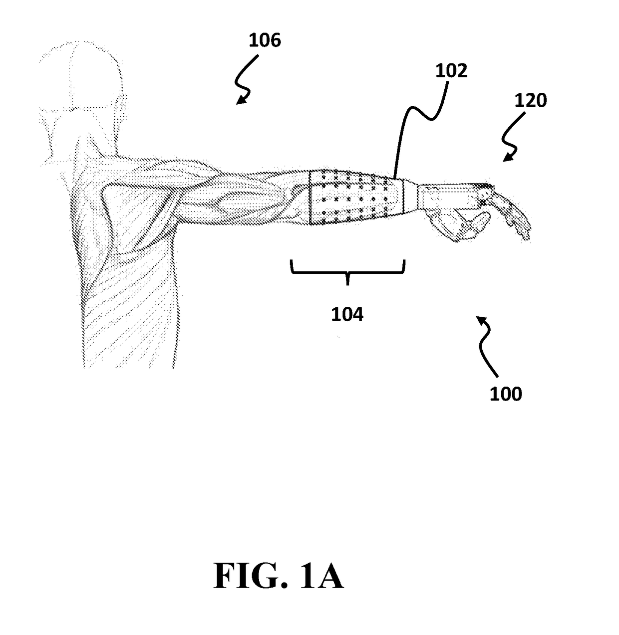
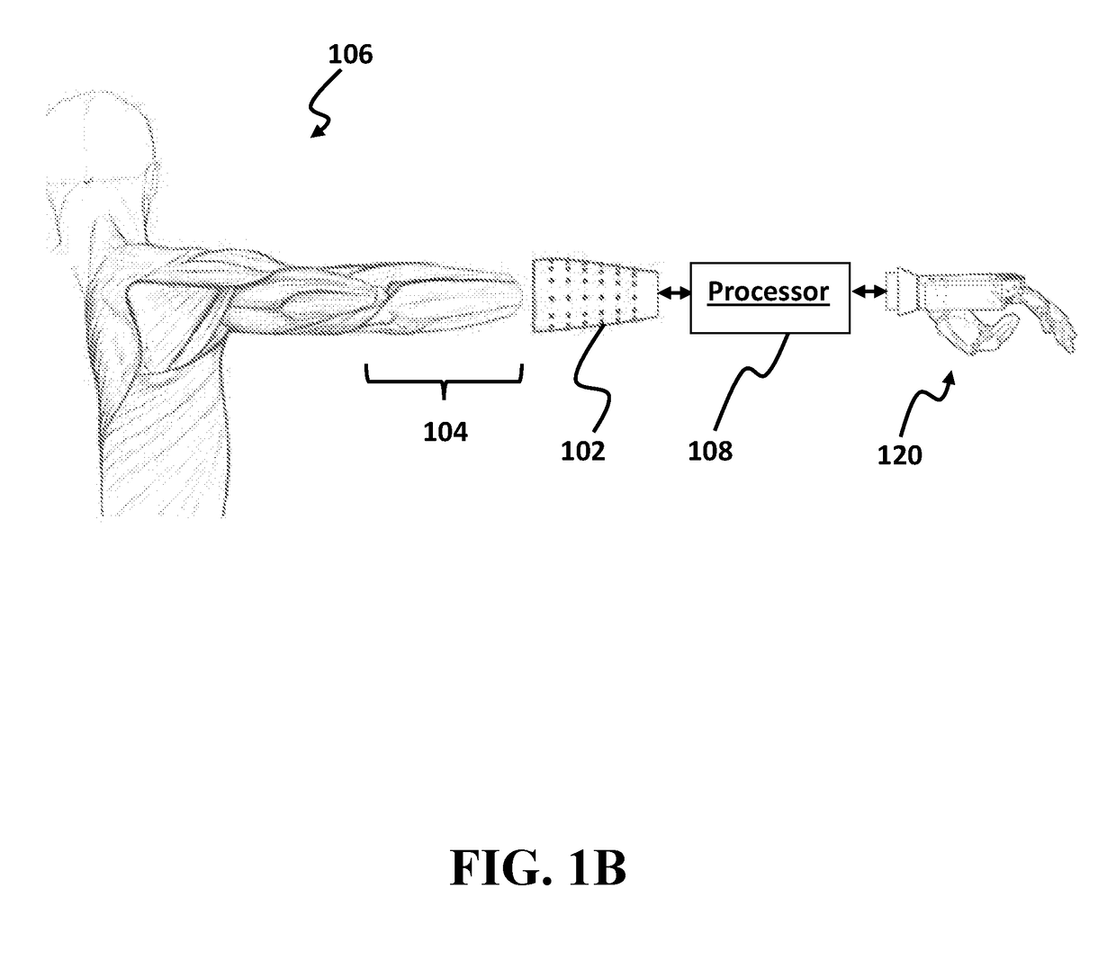
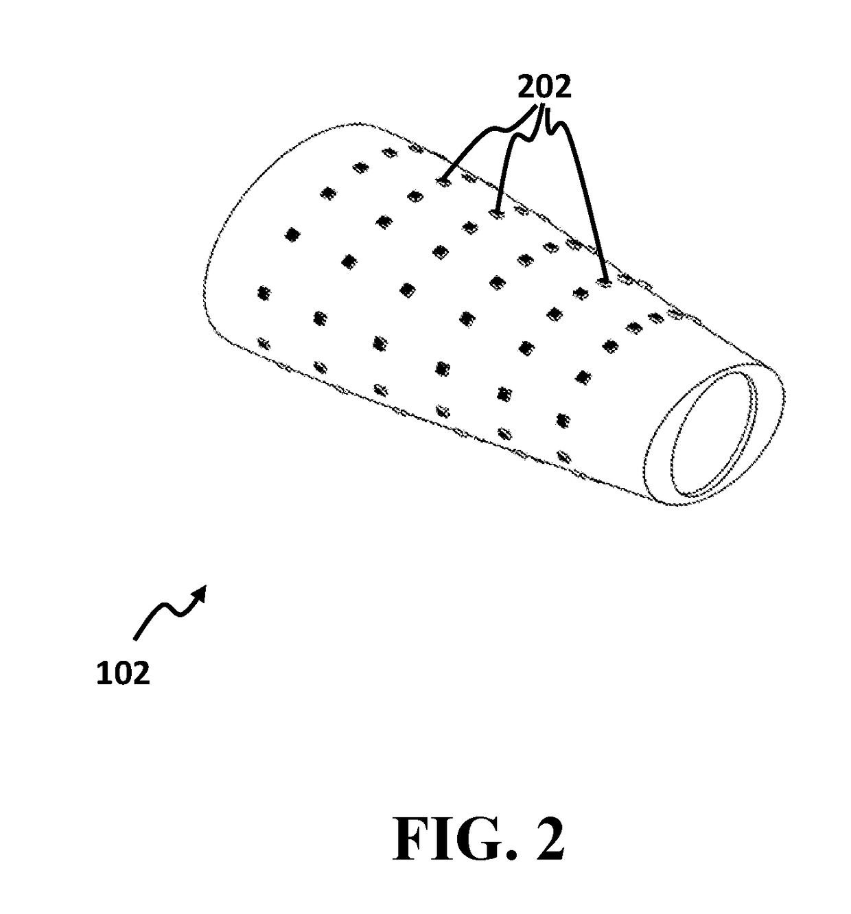
CROSS-REFERENCE TO RELATED APPLICATION[0001]This application claims the benefit of priority from pending U.S. Provisional Patent Application Ser. No. 62 / 528,459, filed on Jul. 4, 2017, and entitled “A CONTROL SYSTEM FOR DETECTING MUSCLE MOVEMENTS” which is incorporated herein by reference in its entirety.TECHNICAL FIELD[0002]The present disclosure generally relates to muscle movements detection systems and methods, and particularly to a system and a method for detecting muscle movements by utilizing implanted passive tags.BACKGROUND[0003]For moving any joint in the body, a signal from brain is needed. In order to move a joint, brain may send a voluntary signal to respective peripheral nerve and, consequently, the nerve may stimulate the specific muscle so that the muscle is contracted and thereby pulling the respective tendon to flex the related joint.[0004]For purpose of reference, it should be understood that any interruption in above cycle may abort the movement intention. For ex...

Claims


Application Information

Patent Timeline
Patent Type & Authority Applications(United States)
IPC IPC(8): A61B5/00A61F2/68A61B5/11A61B90/98A61B5/06A61F2/58
CPCA61B5/4851A61F2/68A61B5/1107A61B5/1127A61B5/4519A61B90/98A61B5/064A61F2/585A61B2090/397A61B2090/3991A61B2090/3908A61B2090/3925A61B2090/3954A61F2002/587A61B2562/046A61B2562/066A61B5/6824A61F2/583A61F2/72A61F2/76A61F2/7812A61F2002/6863A61F2002/701A61F2002/704A61F2002/7615A61F2002/762A61F2002/7837
Inventor MORADI, ALIVAHEDI, EHSANKERMANI, SAEEDEBRAHIMZADEH, MOHAMMAD HOSEINAKBARZADEH TOOTOONCHI, ALIREZABAHRAMI MOQADAM, SAEEDJAFARZADEH, HAMEDPISHBIN, SEYEDPOUYA
Owner MORADI ALI
Why Eureka
Try Eureka