
Pillar framework structure and vehicle body module structure

Active Publication Date: 2019-01-03
TOYOTA JIDOSHA KK
View PDF0 Cites 7 Cited by
  • Summary
  • Abstract
  • Description
  • Claims
  • Application Information

AI Technical Summary

Benefits of technology

The present disclosure provides a pillar framework structure and a vehicle body module structure that can improve coupling rigidity and disperse collision load in a collision. The pillar framework structure involves joining the pillar lower and upper together through a joining member that configures a node, and the cowl reinforcement can also be joined to the joining member. The vehicle body module structure involves joining multiple vehicle body modules together through the joining member, reducing manufacturing processes and improving coupling rigidity. Overall, the present disclosure enhances the stability and safety of the vehicle body structure.

Problems solved by technology

Moreover, there is a concern that if the coupling rigidity is low, collision load might not be well-dispersed between the respective framework members in a collision.

Method used


Image

  • Pillar framework structure and vehicle body module structure
  • Pillar framework structure and vehicle body module structure
  • Pillar framework structure and vehicle body module structure

Examples


Embodiment Construction

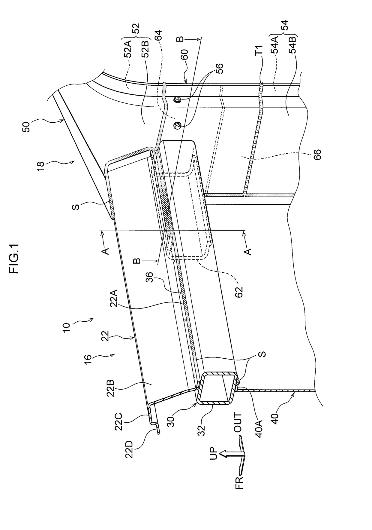
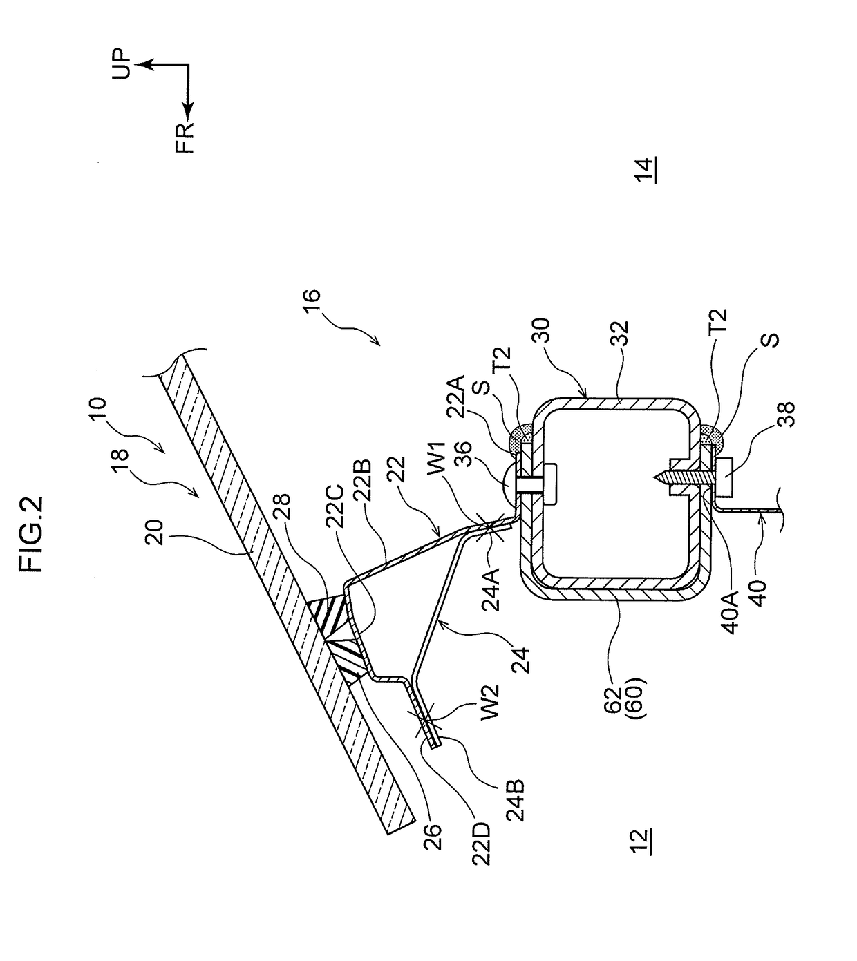
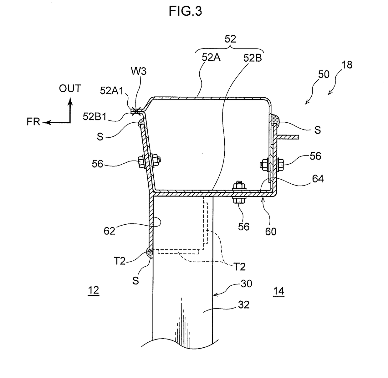
[0023]Explanation follows regarding a pillar framework structure according to an exemplary embodiment of the present disclosure, with reference to FIG. 1 to FIG. 3. In each of the drawings, the arrow FR indicates a vehicle front direction, the arrow UP indicates a vehicle upward direction, and the arrow OUT indicates a vehicle width direction outer side. A front section of a vehicle is configured with basic left-right symmetry, and so only the right of the vehicle is illustrated and described.

[0024]FIG. 1 and FIG. 2 illustrate a cowl section 16 and a front pillar 50 of a vehicle 10 applied with a pillar framework structure 18. Note that windshield glass 20 is omitted from illustration in FIG. 1. The cowl section 16 of the vehicle 10 is provided between the front pillars 50, these being pillars at both vehicle width direction ends of the cowl section 16. As illustrated in FIG. 1 and FIG. 2, the cowl section 16 is configured including a cowl top panel 22 that supports the windshield g...


PUM


Abstract

There is provided a pillar framework structure including: a pillar lower that extends in a vehicle vertical direction; a joining member that is joined to an upper portion of the pillar lower and that is configured from die-cast aluminum; and a pillar upper that is joined to the joining member, and that extends in a vehicle upward direction and a vehicle rearward direction.

Description

CROSS-REFERENCE TO RELATED APPLICATION[0001]This application is based on and claims priority under 35 USC 119 from Japanese Patent Application No. 2017-127818 filed on Jun. 29, 2017, the disclosure of which is incorporated by reference herein.BACKGROUNDTechnical Field[0002]The present disclosure relates to a pillar framework structure and a vehicle body module structure.Related Art[0003]Japanese National-Phase Publication No. 2005-537179 discloses a body structure in which a roof module provided with front and rear roof columns (pillars) is placed on and connected to a base module provided with column portions, these being pillar lower sections. The front and rear roof columns of the roof module are connected to each other by corresponding cross members.[0004]The connections between the respective framework members are made by adhesion or welding. For example, in a front pillar of the body structure of Japanese National-Phase Publication No. 2005-537179, a column portion extending i...

Claims


Application Information

Patent Timeline
IPC IPC(8): B62D25/14B62D25/04B62D25/08B62D27/02B62D27/06
CPCB62D25/145B62D25/04B62D25/081B62D27/02B62D27/065B62D25/06B62D29/008
Inventor TAKII, SHUNSUKE
Owner TOYOTA JIDOSHA KK
Learn More