Pneumatic Tire

Active Publication Date: 2019-01-17
YOKOHAMA RUBBER CO LTD
View PDF4 Cites 18 Cited by
  • Summary
  • Abstract
  • Description
  • Claims
  • Application Information

AI Technical Summary

Benefits of technology

[0005]The present technology relates to a pneumatic tire that can achieve excell

Problems solved by technology

However, with a lug groove having this shape, discharging performance of mud and the like is achieved by increasing the size of the groove width toward the outer side in the tire width direction, and therefore, mud and the like in the lug groove is rather difficult to compact, and a problem occurs where tractio

Method used


Image

  • Pneumatic Tire
  • Pneumatic Tire
  • Pneumatic Tire

Examples


examples

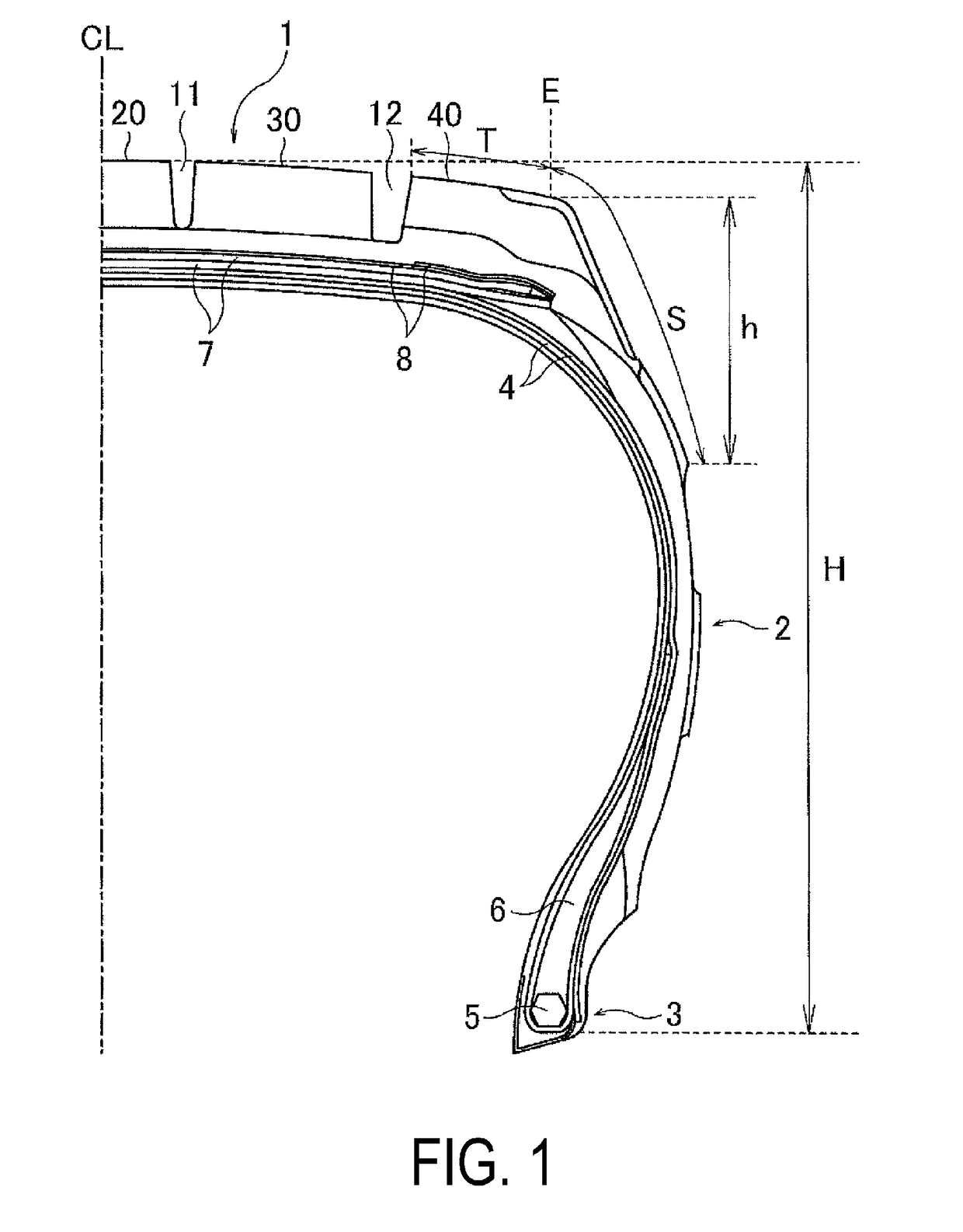
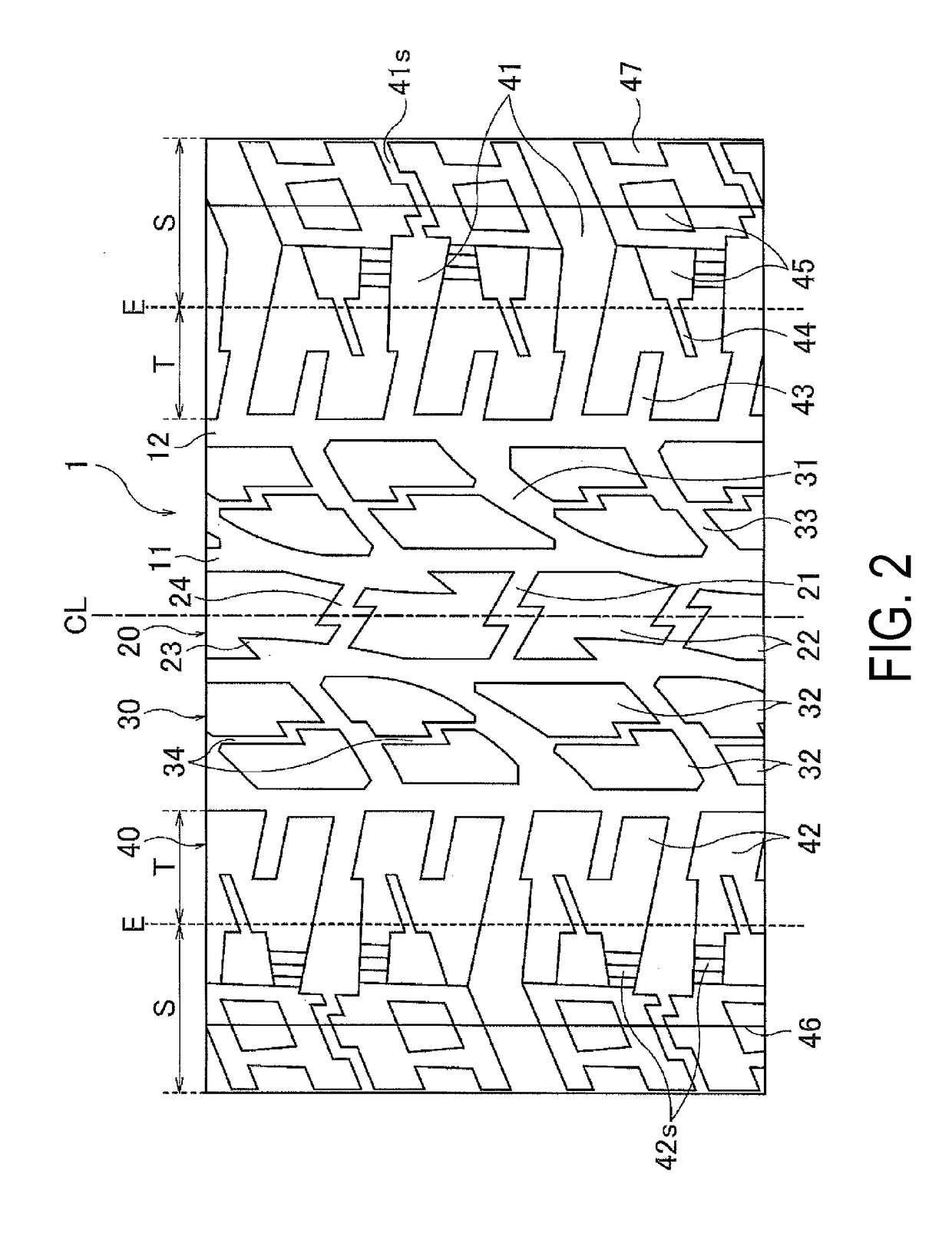
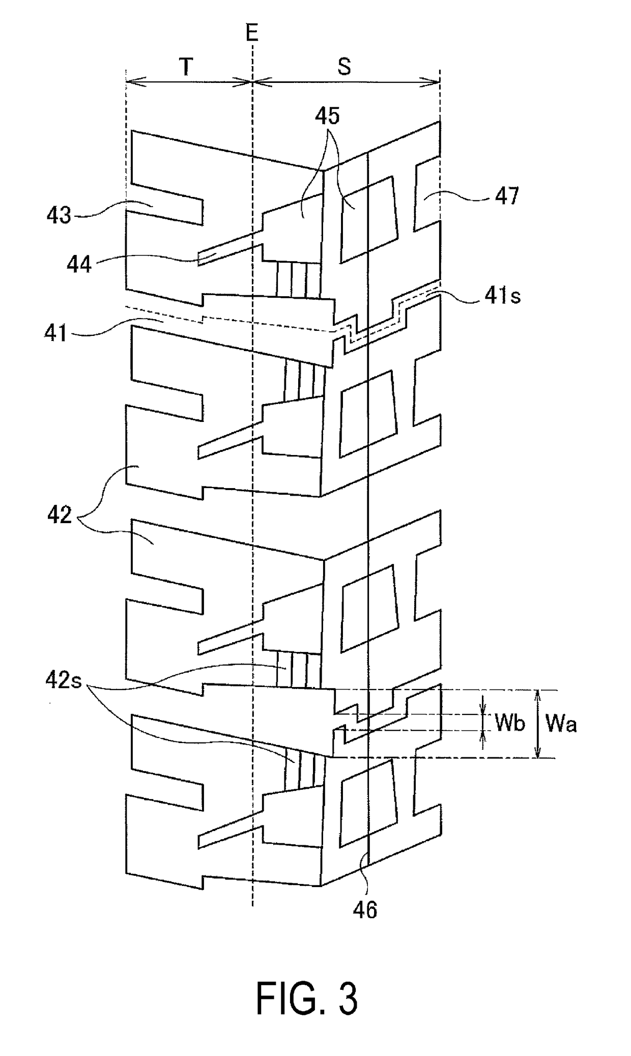
[0064]34 types of pneumatic tires of Conventional Example 1, Comparative Examples 1 to 3, and Examples 1 to 30 were prepared, having a tire size of 265 / 65 R 17 112H, having the basic structure illustrated in FIG. 1, having the structure illustrated in FIG. 2 for a tread pattern within the ground contact region, and for a structure more on the outer side in the tire width direction than the ground contact end, the following were set as shown in Tables 1 to 3: the number of the recessed portions each having a closed periphery, formed in the side region of the shoulder block; the placement of the recessed portions; ratio h / H of the orthogonal distance h from the ground contact end position to the edge on the innermost side in the tire radial direction measured toward the tire radiation direction with regard to the tire cross-sectional height H; the ratio Sin / Sout of the total area Sin of the recessed portions for each of the shoulder blocks and area Sout of the side region for each of ...


PUM


Abstract

A pneumatic tire includes: a main groove extending in a tire circumferential direction disposed on a shoulder region of a tread portion; lug grooves extending from the main groove toward an outer side and reaching a side wall portion; and blocks demarcated by the main groove and lug grooves. An edge on an innermost side in a tire radial direction of the blocks is positioned more on an outer side in the tire radial direction than a tire maximum width position, and a ratio of an orthogonal distance from a ground contact end position to the edge on an innermost side in the tire radial direction of the blocks is 0.2 or more. Recessed portions each having a closed periphery are provided in a side region more on an outer side in a tire width direction than the ground contact end of the blocks.

Description

TECHNICAL FIELD[0001]The present technology relates to a pneumatic tire, and particularly relates to a pneumatic tire that can achieve excellent running performance on muddy ground, snowy roads, sandy ground, or the like.BACKGROUND ART[0002]A pneumatic tire with a tread pattern primarily having a lug groove with a high amount of edge components, and with a large groove area or groove depth is generally used for a pneumatic tire used in traveling on muddy ground, snowy roads, sandy ground, and the like (hereinafter, referred to as muddy ground or the like). With this tire, traction performance is achieved by engaging with mud, snow, sand, and the like (hereinafter, referred to as mud and the like) on a road surface, and mud and the like is prevented from packing into the groove (discharging performance of mud and the like is increased), and thus running performance on muddy ground and the like (mud performance) is improved (for example, refer to Japanese Unexamined Patent Application...

Claims


Application Information

Patent Timeline
IPC IPC(8): B60C11/01B60C11/03B60C11/12
CPCB60C11/01B60C11/0306B60C11/1204B60C2200/14B60C2011/013B60C2011/036B60C2011/1213B60C11/1236B60C2011/0365B60C2011/0348B60C3/04B60C11/03B60C2200/04
Inventor YAMAKAWA, TAKAHIRO
Owner YOKOHAMA RUBBER CO LTD
Why Eureka
Try Eureka