Liquid level detection in receptacles

a technology of liquid level detection and receptacles, which is applied in the field of contactless measurement, can solve the problems of accuracy limitations which are overcome, conventional methods do not have a sufficiently high resolution to take into account,

Active Publication Date: 2019-01-17
CSEM CENT SUISSE DELECTRONIQUE & DE MICROTECHNIQUE SA RECH & DEV
View PDF6 Cites 4 Cited by
  • Summary
  • Abstract
  • Description
  • Claims
  • Application Information

AI Technical Summary

Benefits of technology

[0023]The invention further relates to an apparatus for measuring a volume of liquid provided in at least one receptacle such as a well of a well plate, a test tube, a petri dish or similar. This apparatus comprises a support for receiving a receptacle which has at least one cavity for holding a liquid, a plenoptic camera facing said support, as well as a control unit communicating with at least said camera and adapted to carry out any of the variants of methods as outlined above. By “adapted”, it is meant that the control unit is not merely capable of carrying out the method, but that it is indeed programmed or otherwise set up to do so. As already discussed above, such cameras, also referred to as light field cameras, record not only the colour and intensity of light reaching them, but also the direction each light ray is travelling, and as a result 3D data can be gleaned from the plenoptic images generated by them, and as a result the surface topography of the liquid can be determined and processed so as to measure the volume of the liquid precisely, including that represented by the meniscus.
[0024]Advantageously, the plenoptic camera is mounted on a scanning stage movable perpendicular to the optical axis of said plenoptic camera. As a result, the camera can be moved so as to image multiple wells of a multi-well plate without moving the plate itself, thus without risking disturbing the surface of the liquid.

Problems solved by technology

Conventional methods do not have a sufficiently high resolution to take into account the meniscus, which can represent a significant proportion of the volume in the case of very small liquid samples.
This results in accuracy limitations which are overcome by the present method.

Method used


Image

  • Liquid level detection in receptacles
  • Liquid level detection in receptacles
  • Liquid level detection in receptacles

Examples


Embodiment Construction

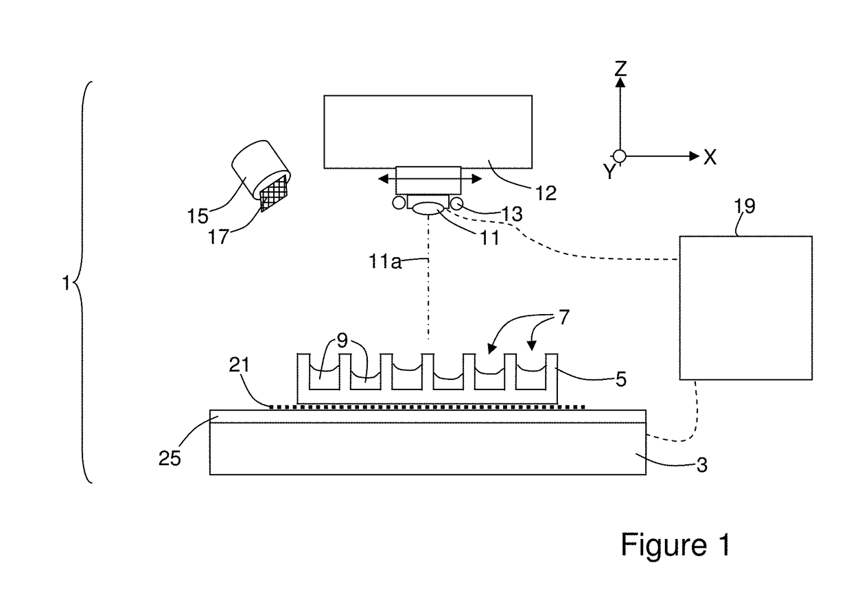
[0038]The present invention exploits the properties of plenoptic cameras, also known as light-field cameras, in order to measure the volume of liquid in a well (i.e. a cavity) of a multi-well plate. Conventional digital cameras measure only the intensity and colour of light arriving on each pixel of a sensor, and hence create two-dimensional images. Plenoptic cameras, by contrast, capture information about the light field emanating from the subject being imaged. In doing so, information is measured regarding the direction of travel of each light ray captured by the camera. Such cameras typically comprise an array of microlenses placed one focal length away from the image plane of a sensor, and are commercially available from the manufacturers Raytrix and Lytro, amongst others.

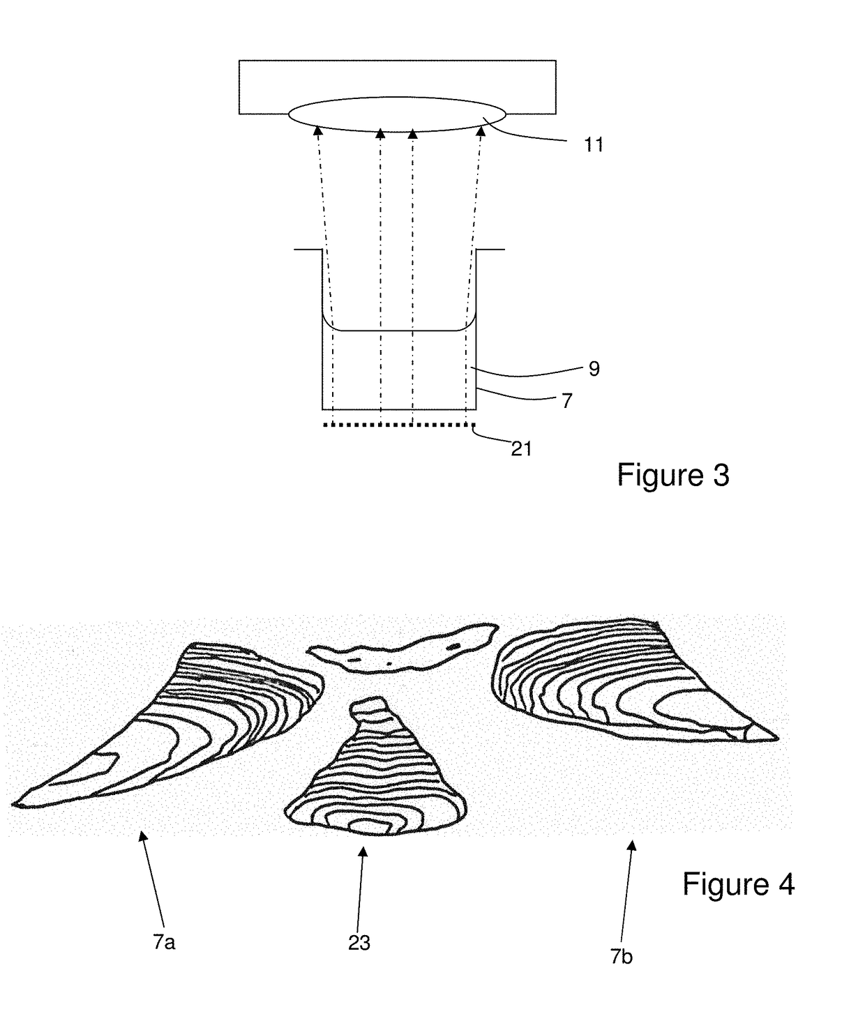
[0039]By processing the data relating to the intensity, colour and direction of travel of the lights rays detected by such plenoptic cameras, 3D models of the subject being imaged can be generated. Generation o...


PUM


Abstract

Disclosed is a method of measuring a volume of a liquid provided in at least one receptacle, including the steps of: providing a receptacle having at least one cavity for holding a liquid; providing a plenoptic camera positioned so as to be able to image the surface of the liquid; positioning the receptacle such that the liquid surface faces an objective lens of the plenoptic camera; making at least one plenoptic image of the surface of the liquid by way of the plenoptic camera; determining a surface topography of the liquid on the basis of the at least one image; calculating the volume of liquid based on the measured surface topography and at least one known dimension and/or position of the cavity.

Description

TECHNICAL FIELD[0001]The present invention relates to the technical field of contactless measurement of the fill level of liquids in receptacles such as multi-well plates used in life sciences.STATE OF THE ART[0002]Multi-well plates are arrays of receptacles incorporated into a single container in an array, and are used typically for assays (e.g. bioassays, immunoassays and so on) as well as for culturing cells, tissue samples and so on. Such plates allow researchers to carry out large numbers of tests in parallel in a single multi-well plate (with typically between 6 and over 1536 on a single plate), which helps to efficiently perform large numbers of tests in substantially identical conditions since the atmospheric conditions (temperature, pressure, heat) are guaranteed identical for each well of the plate.[0003]In many types of such assays, it is important to know the fill level of the liquid in the wells, and hence its volume. This information can be used to guarantee an equal v...

Claims


Application Information

Patent Timeline
Patent Type & Authority Applications(United States)
IPC IPC(8): G01F22/00G01F23/22G06T7/62H04N13/296H04N5/232
CPCG01F22/00G01F23/22G06T7/62B01L3/5082H04N5/23299G06T2207/10052B01L3/5085H04N13/296G01F23/292H04N23/695
Inventor KNAPP, HELMUTSCHMID, PHILIPPBEYER, CHRISTIANHOCHEMER, MATTHIASREVOL, VINCENT
Owner CSEM CENT SUISSE DELECTRONIQUE & DE MICROTECHNIQUE SA RECH & DEV
Why Eureka
Try Eureka