Zoom lens and optical instrument

a zoom lens and optical instrument technology, applied in the field of telephoto zoom lenses, can solve the problems of difficult difficult to achieve favorable optical performance, in particular at the shortest distance, and difficult to have high-speed focusing, so as to reduce the total length of the zoom lens and reduce the weight. , the effect of small movemen

Active Publication Date: 2019-01-17
SONY CORP
View PDF4 Cites 5 Cited by
  • Summary
  • Abstract
  • Description
  • Claims
  • Application Information

AI Technical Summary

Benefits of technology

[0007]Further, in recent years, there has been a demand, also in an interchangeable-lens digital camera, for a zoom lens system optimized for photographing of not only a still image, but also a moving image. It is necessary, in the photographing of a moving image, to cause a lens group that performs focusing to travel at a high speed in order to follow a quick motion of a subject. Accordingly, it is requested for the focusing lens group to have a small amount of movement and to have a reduced weight.
[0008]It is desirable to provide a zoom lens that makes it possible to achieve reduction in total length thereof as well as reduction in size and weight of a focusing lens group while having a high image-forming performance, and an optical instrument mounted with such a zoom lens.
[0012]The zoom lens or the optical instrument according to an embodiment of the disclosure has an overall six-group configuration in which the first lens group includes the front side first lens group and the rear side first lens group, and in which at least two lens groups including the rear side first lens group travel along the optical axis upon focusing, thus making it possible to achieve reduction in a total length thereof as well as reduction in size and weight of a focusing lens group while having a high image-forming performance.

Problems solved by technology

In the zoom lens disclosed in PTL 1, however, a focusing lens group is present only in a first lens group, which necessitates a long focusing stroke, making it difficult to reduce a total length of the zoom lens and making it difficult to have a high-speed focusing.
Further, a focusing system in which only one lens group travels has a large aberration variation due to the focusing, making it difficult to achieve a favorable optical performance, in particular, at a shortest distance.
However, a long focusing stroke is still necessary, making it difficult to reduce a total length of the zoom lens.

Method used


Image

  • Zoom lens and optical instrument
  • Zoom lens and optical instrument
  • Zoom lens and optical instrument

Examples


numerical example 1

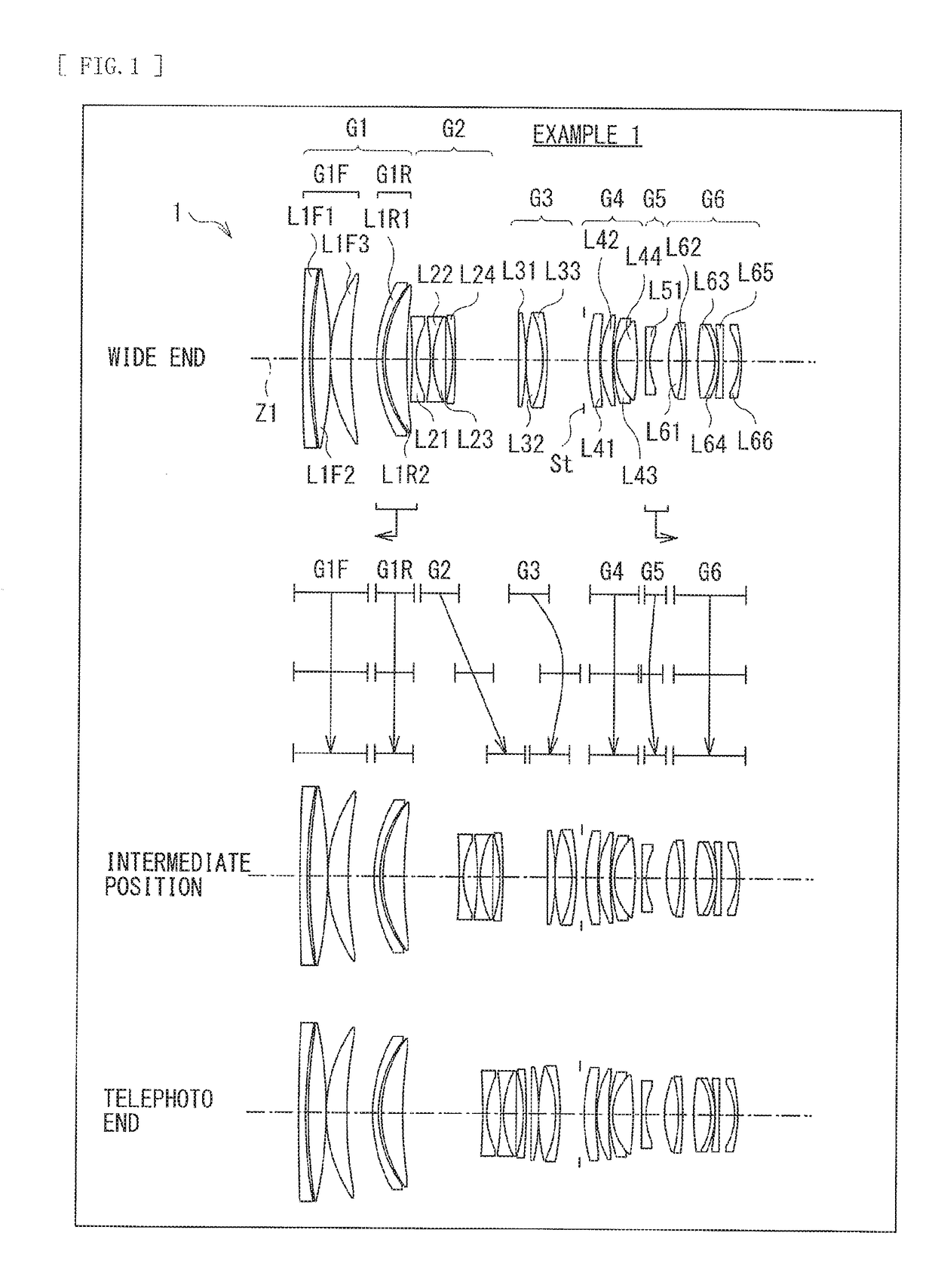
[0107]Table 1 indicates basic lens data of Numerical Example 1 in which specific numerical values are applied to the zoom lens 1 illustrated in FIG. 1. Further, Table 2 indicates coefficient values in aspherical surfaces. Furthermore, Table 3 indicates values of a focal length f of an entire lens system, F number (FNo.), the half angle of view ω, and a lens total length at each of the wide end (the short focal length end), the intermediate position (the standard angle of view, the intermediate focal length), and the telephoto end (the long focal length end).

[0108]Moreover, Table 3 also indicates values of variable surface intervals. In Numerical Example 1, values of surface intervals d10, d17, d22, d30, and d32 vary upon zooming.

[0109]In the zoom lens 1 according to Numerical Example 1, the rear side first lens group G1R and the fifth lens group G5 each serve as a focusing lens group. The rear side first lens group G1R travels toward the object side along the optical axis upon focus...

numerical example 2

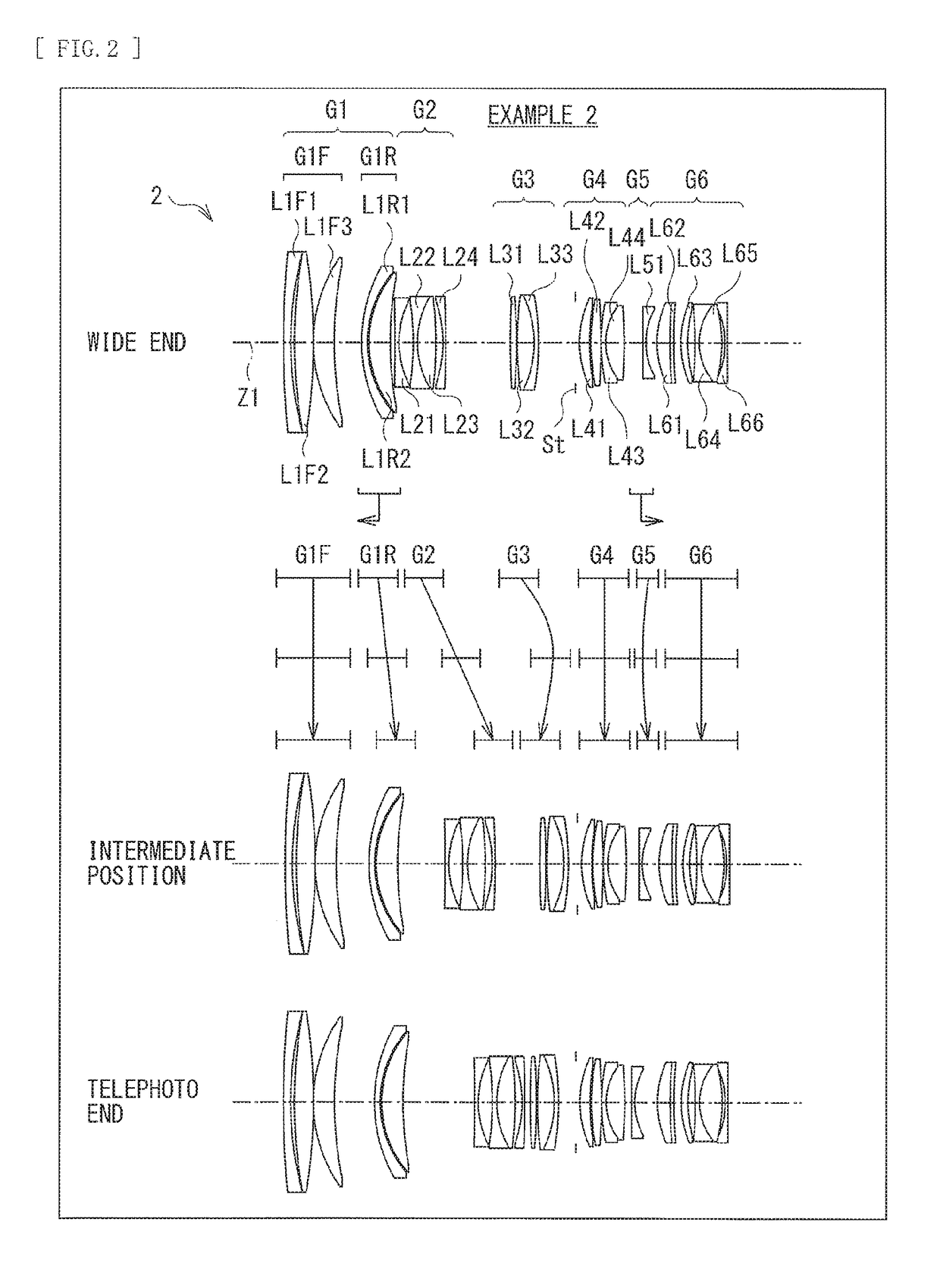
[0121]Table 4 indicates basic lens data of Numerical Example 2 in which specific numerical values are applied to the zoom lens 2 illustrated in FIG. 2. Further, Table 5 indicates coefficient values in a spherical surfaces. Furthermore, Table 6 indicates values of a focal length f of an entire lens system, F number (FNo.), the half angle of view ω, and a lens total length at each of the wide end (the short focal length end), the intermediate position (the standard angle of view, the intermediate focal length), and the telephoto end (the long focal length end).

[0122]Moreover, Table 6 also indicates values of variable surface intervals. In Numerical Example 2, values of surface intervals d6, d10, d17, d22, d30, and d32 vary upon zooming.

[0123]In the zoom lens 2 according to Numerical Example 2, the rear side first lens group G1R and the fifth lens group G5 each serve as a focusing lens group. The rear side first lens group G1R travels toward the object side along the optical axis upon ...

numerical example 3

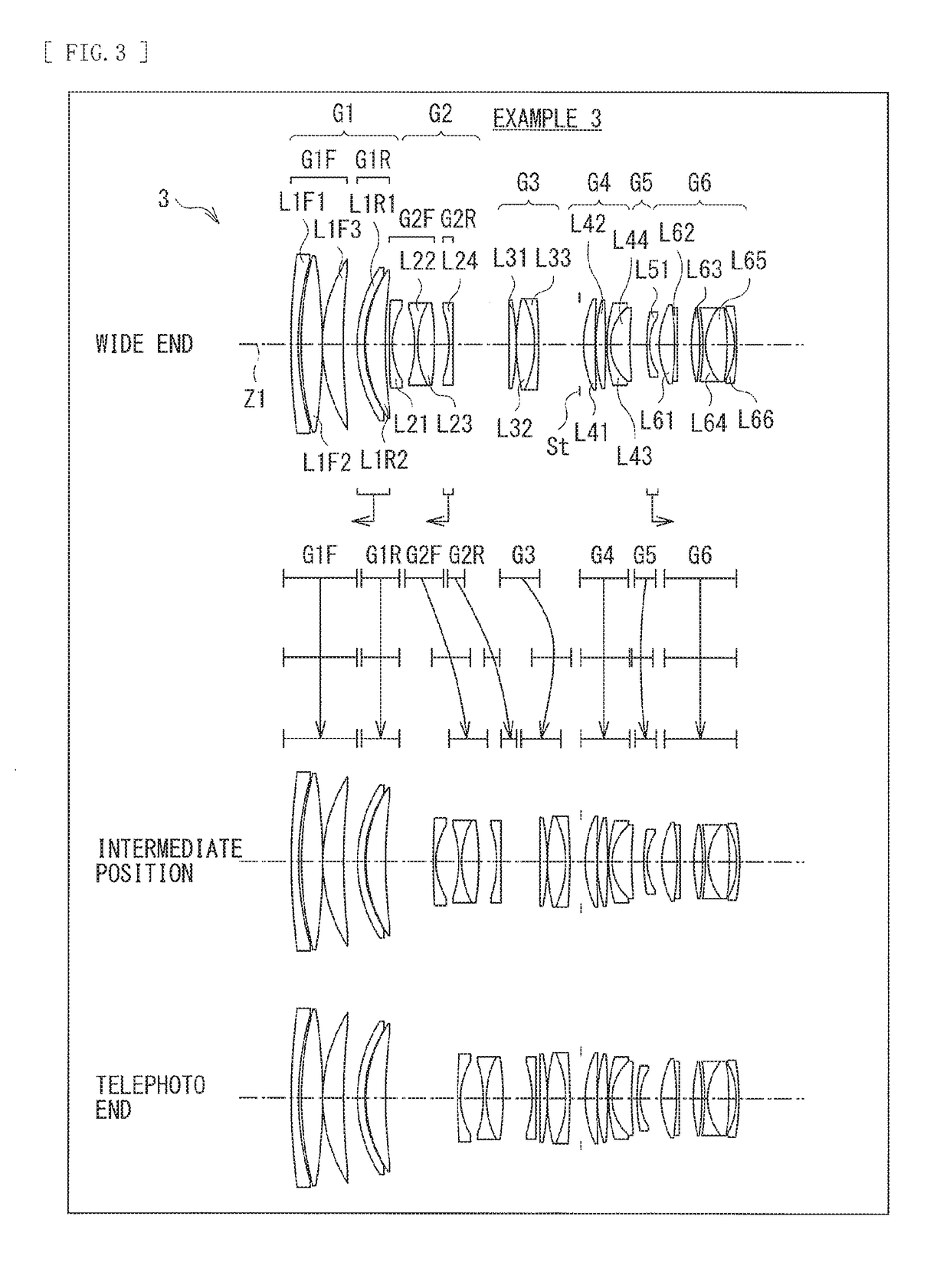
[0136]Table 7 indicates basic lens data of Numerical Example 3 in which specific numerical values are applied to the zoom lens 3 illustrated in FIG. 3. Further, Table 8 indicates coefficient values in aspherical surfaces. Furthermore, Table 9 indicates values of a focal length f of an entire lens system, F number (FNo.), the half angle of view w, and a lens total length at each of the wide end (the short focal length end), the intermediate position (the standard angle of view, the intermediate focal length), and the telephoto end (the long focal length end).

[0137]Moreover, Table 9 also indicates values of variable surface intervals. In Numerical Example 3, values of surface intervals d10, d15, d17, d22, d30, and d32 vary upon zooming.

[0138]In the zoom lens 3 according to Numerical Example 3, the negative lens, of the second lens group G2, positioned closest to the image plane side, in addition to the rear side first lens group G1R and the fifth lens group GS, serves as a focusing le...


PUM


Abstract

A zoom lens according to the disclosure includes a first lens group having positive refractive power, a second lens group, a third lens group, a fourth lens group, a fifth lens group, and a sixth lens group. The first lens group includes a front side first lens group fixed with respect to an image plane upon zooming from a wide end to a telephoto end and focusing from an infinite object to a short-distance object, and a rear side first lens group having positive refractive power. The second, third, and fifth lens groups travel along an optical axis upon zooming. The fourth and sixth lens groups are fixed with respect to the image plane in an optical axis direction upon zooming. At least two lens groups including the rear side first lens group travel along the optical axis upon focusing.

Description

TECHNICAL FIELD[0001]The disclosure relates to a telephoto zoom lens of an internal focusing system and an optical instrument. More particularly, the disclosure relates to a zoom lens using a focusing system that is suitably used, especially, for a single-lens reflex camera, a non-reflex camera, and a digital still camera, etc. and that is able to perform favorable aberration correction throughout an overall object distance from infinite to a short distance, and to an optical instrument including such a zoom lens.BACKGROUND ART[0002]For example, PTLs 1 and 2 have proposed a F2.8 class telephoto zoom lens suitable for a photographic camera, a digital still camera, a video camera, and the like.CITATION LISTPatent Literature[0003]PTL 1: Japanese Unexamined Patent Application Publication No. 2012-93548[0004]PTL 2: Japanese Unexamined Patent Application Publication No. 2010-191336SUMMARY OF THE INVENTION[0005]In the zoom lens disclosed in PTL 1, however, a focusing lens group is present ...

Claims


Application Information

Patent Timeline
Patent Type & Authority Applications(United States)
IPC IPC(8): G02B13/18G02B15/20G02B15/177G02B9/62
CPCG02B13/18G02B15/20G02B13/009G02B9/62G02B15/177G02B15/173G02B15/1461
Inventor MIYAGAWA, NAOKICHEN, YONGHUA
Owner SONY CORP
Why Eureka
Try Eureka