
Assembly procedure for a long-stator linear motor

Inactive Publication Date: 2019-01-17
B&R IND AUTOMATION GMBH
View PDF0 Cites 0 Cited by
  • Summary
  • Abstract
  • Description
  • Claims
  • Application Information

AI Technical Summary

Benefits of technology

The invention relates to a way to attach a power electronic unit to a long-stator linear motor easily and quickly while minimizing stress on the unit. This is achieved by using a socket on the transport segment to hold a contact element of the drive coil, inserting a clamping element into the socket with a clamping section, and connecting the power electronic unit to the clamping section through a soldering or plugging process. Multiple sockets and clamping elements can be used for a more complex connection. The use of a cutting and clamping element makes it easy to create an electroconductive connection with the insulated wire used for the drive coil. The connection between the power electronic unit and the clamping element is simple as they both have clip-connection sections. The power electronic unit is enclosed by a closed surface when connected to the clamping element, providing added protection. Overall, the invention simplifies the assembly process and reduces stress on the power electronic unit.

Problems solved by technology

To that end, the wires of the individual drive coils are, for example, attached and soldered to the corresponding contact points of the circuit board, which, however, because of the narrow space available, requires a very complex process control, which is disadvantageous.
Due to the generally very large number of drive coils and the narrow spatial conditions, it is not possible to tighten all screw connections at the same time, or only with a lot of effort.
Although a sequential tightening of the screw connections would be possible, this would prolong the assembly time, which is disadvantageous.
Moreover, both the screwing and the soldering of the wires of the drive coils onto the circuit board requires stripping off the insulation of the wires of the drive coils, which are typically enameled wires, beforehand, which is very expensive and time-consuming and therefore disadvantageous.
Thus, the prior art does not describe any satisfactory solutions that guarantee that no impermissibly high forces will be applied to the circuit board during the assembly of transport segments of a long-stator linear motor.

Method used


Image

  • Assembly procedure for a long-stator linear motor
  • Assembly procedure for a long-stator linear motor

Examples


Embodiment Construction

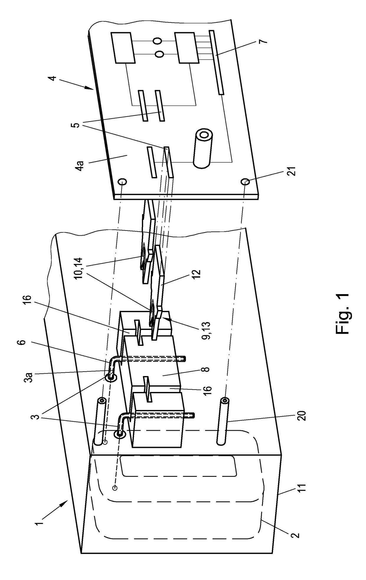
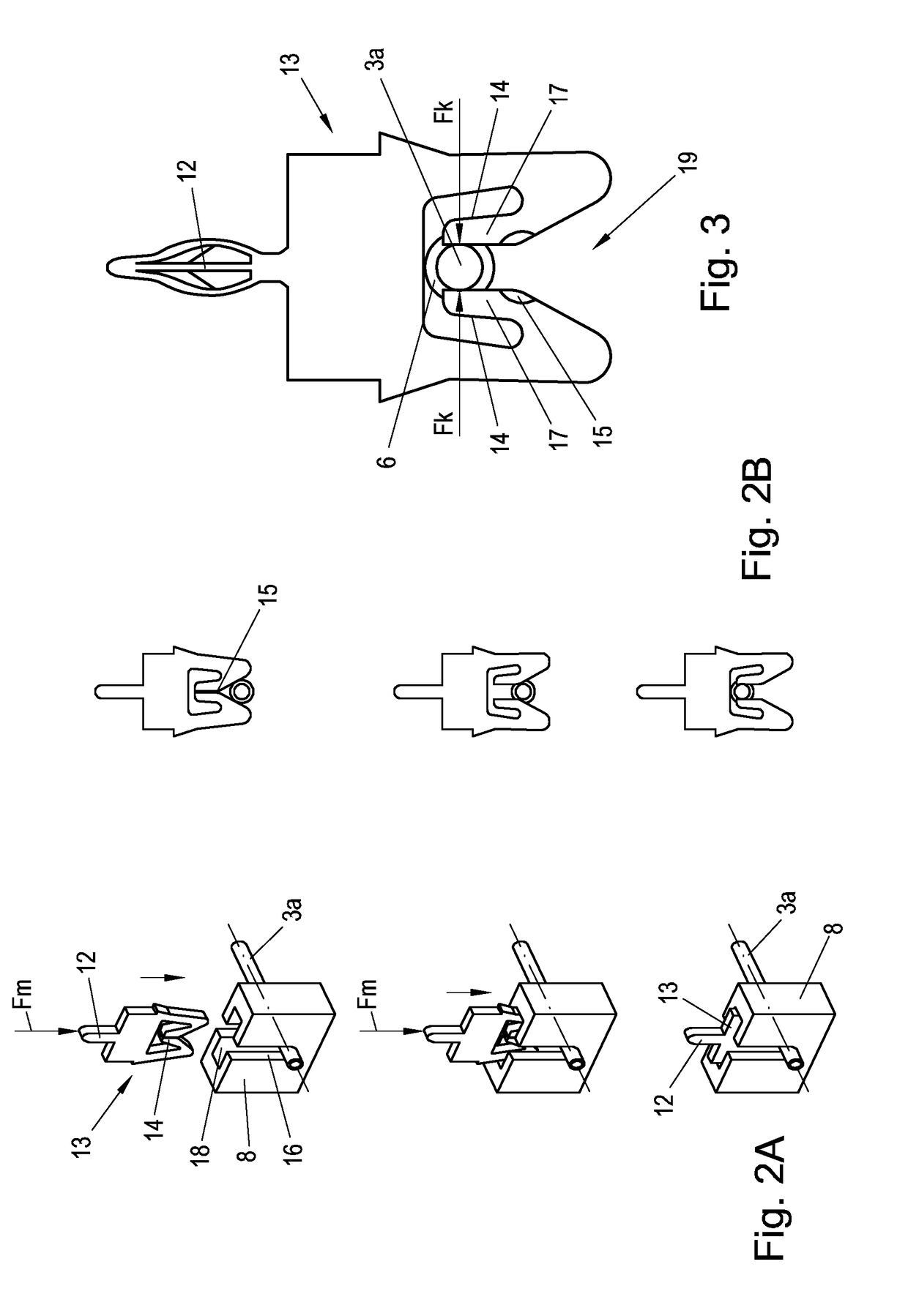
[0008]Accordingly, it is an aim of the invention to create a simple and quick assembly procedure for assembling on the transport segment a power electronic unit of a transport segment of a long-stator linear motor, with the lowest possible stress placed on the power electronic unit during assembly.

[0009]According to the invention, the problem is solved by arranging on the transport segment at least one socket for accommodating at least one contact element of the drive coil, arranging the at least one contact element of the drive coil in the socket, inserting at least one clamping element corresponding to the socket into the socket with a clamping section, wherein the contact element of the drive coil, while creating an electroconductive connection to the clamping section of the clamping element, is fixed in the socket by the clamping element, and that at least one contact point of the power electronic unit, while creating an electroconductive connection, is directly connected to a c...


PUM


Abstract

Procedure mounting at least one power electronic unit of a transport segment of a long-stator linear motor onto the transport segment. At least one socket is arranged on the transport segment to accommodate at least one contact element of the drive coil arranged in the socket. At least one clamping element is inserted into the socket with a clamping section. The contact element of the drive coil, while creating an electroconductive connection to the clamping section of the clamping element, is fixed into the socket by the clamping element. At least one contact point of the at least one power electronic unit, while creating an electroconductive connection, is connected directly to a connecting section of the clamping element. The contact element is first arranged in the socket, then the clamping element is inserted into the socket, and then the contact point is connected directly to the connecting section.

Description

CROSS-REFERENCE TO RELATED APPLICATIONS[0001]The present application claims priority under 35 U.S.C. § 119(a) of Austria Patent Application No. A50577 / 2017 filed Jul. 12, 2017, the disclosure of which is expressly incorporated by reference herein in its entirety.BACKGROUND OF THE INVENTION1. Field of the Invention[0002]The invention relates to an assembly procedure for connecting at least one power electronic unit to a transport segment of a long-stator linear motor, wherein the transport segment comprises at least one drive coil with at least two contact elements and the at least one power electronic unit comprises at least two contact points that correspond to the contact elements of the drive coil, wherein an electroconductive connection between the contact elements of the drive coil and the contact points of the at least one power electronic unit is created.2. Discussion of Background Information[0003]In one sufficiently known long-stator linear motor, a plurality of electrical ...

Claims


Application Information

Patent Timeline
IPC IPC(8): H02K15/00H02K5/22H02K41/02
CPCH02K15/0068H02K41/02H02K5/225H02K11/33H01R4/242H02K3/52H02K2203/03H05K3/325H02K15/00B60L13/03H01R4/2425
Inventor REINTHALER, MICHAELSTOJCIC, GORAN
Owner B&R IND AUTOMATION GMBH
Learn More